Control a Pan and Tilt Servo with an Arduino Mega and Joystick

Live project track
Think about how your neck and head move together to look around a room. You turn left or right, and you look up or down. Combining those two simple movements allows your eyes to point at any object in the entire space.
In this project, two servo motors do that exact job. An analog thumb joystick reads where your hand pushes, and an Arduino Mega turns both motors to follow your movement. The main lesson is: the joystick changes electrical signals when you move it, and the Arduino translates those signals into precise motor angles.
How Two Servos Work Together to Aim in Any Direction
A single servo motor can only rotate back and forth along one flat line. But when you mount a second servo directly on top of the first one at a right angle, you create a turret that can aim in two dimensions.
The bottom servo handles Pan (turning left and right). The top servo handles Tilt (pointing up and down). Working together, they let a camera mount, sensor bracket, or pointer reach almost any angle you want.
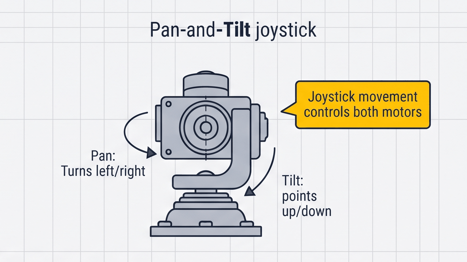
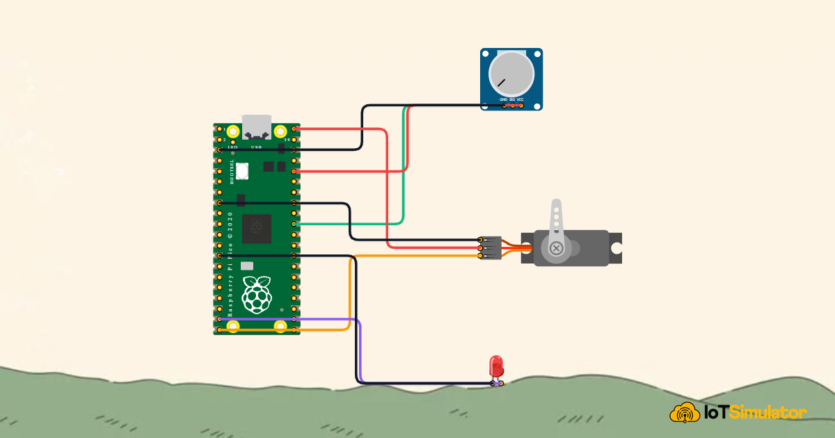
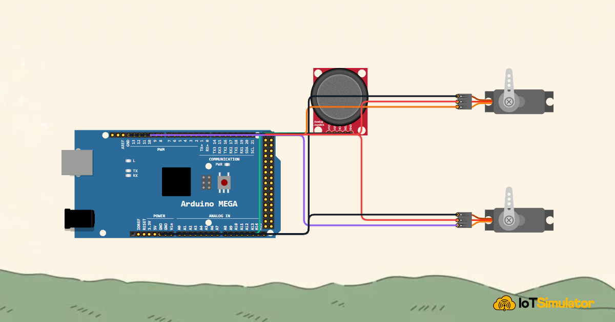
The diagram above illustrates how the Arduino Mega coordinates the entire system. As you push the thumbstick on the left, it feeds analog readings to pins A0 and A1. The Arduino calculates the target positions and sends control pulses from digital pins 9 and 10 to turn both servos in real time.
| Component | Movement | Arduino Pin | Role in Circuit |
|---|---|---|---|
| Pan Servo | Left and Right | Pin 9 | Rotates the bottom base horizontally |
| Tilt Servo | Up and Down | Pin 10 | Tilts the top mount vertically |
| Joystick | 2 Directions | Pins A0 & A1 | Measures your thumb position |
Because the Arduino Mega controls both motors simultaneously in each cycle, you can easily point diagonally by moving both servos at the exact same moment.
How the Joystick Reads Your Thumb Movement
Underneath the thumbstick are two small rotary resistors called potentiometers. Moving the stick rotates these internal sensors just like adjusting a volume knob.
When the stick rests in the center, both sensors output approximately 2.5V. Moving the stick all the way to one edge drops the voltage to 0V, while pushing to the opposite edge raises it to 5V. The Arduino reads this voltage range as a number between 0 and 1023.
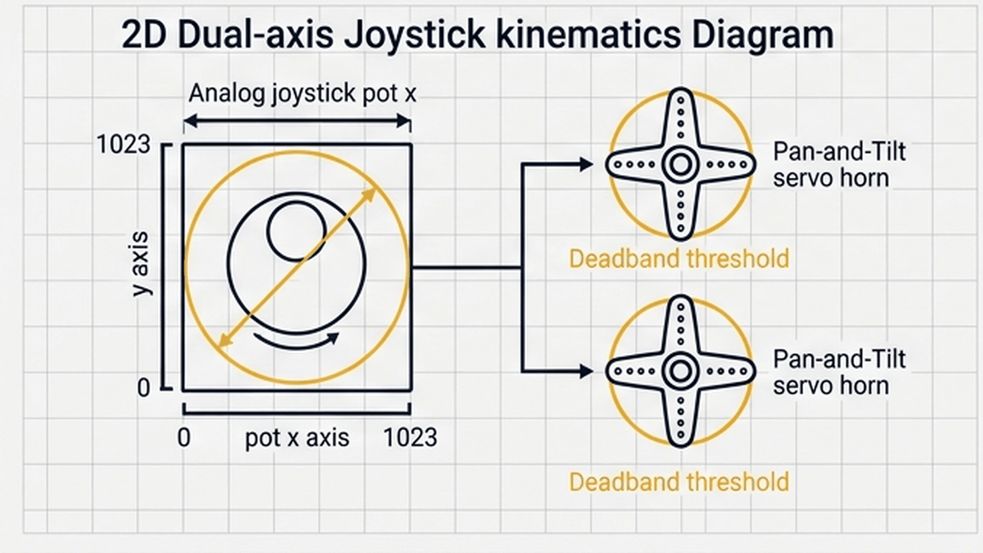
The process diagram above shows how thumb movement immediately controls the servo horn. As your thumb pushes right, the analog reading increases, and the Arduino commands the servo to rotate right to match.
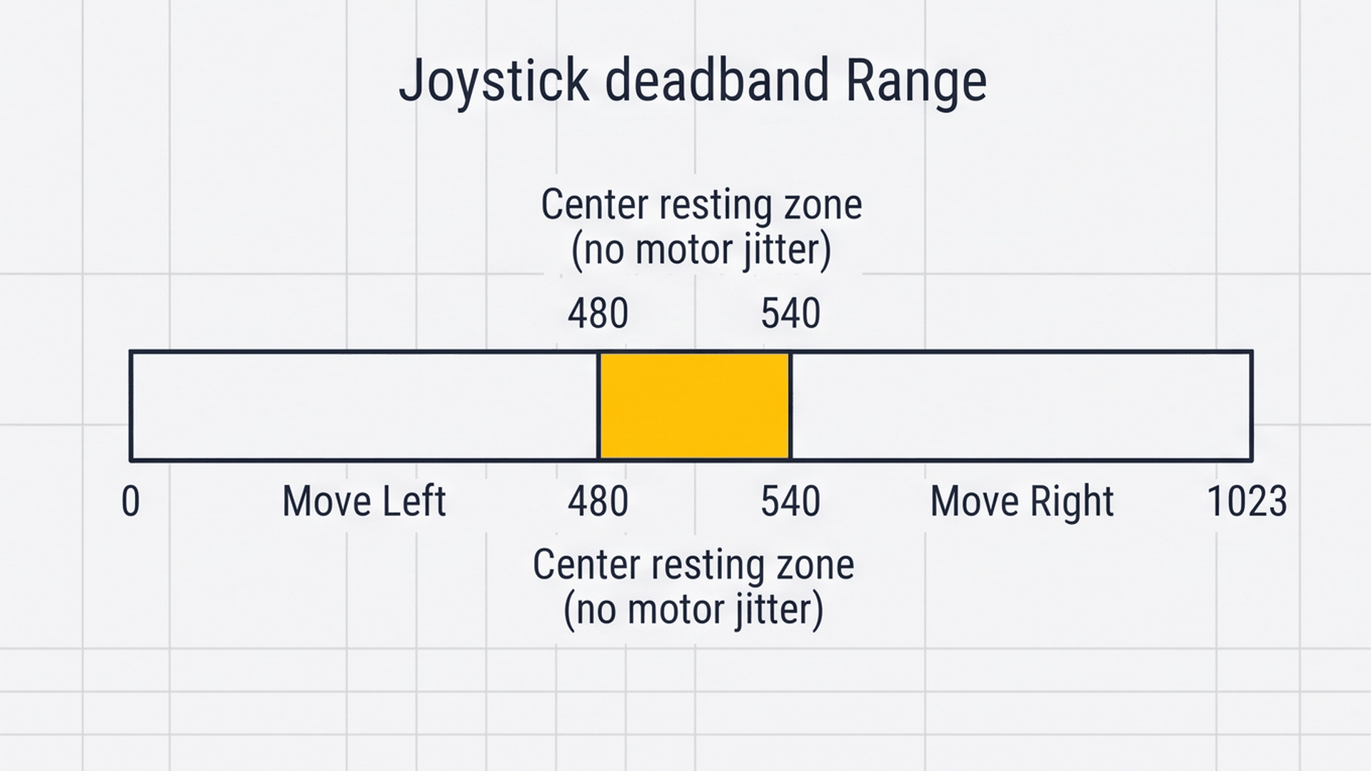
When you release your thumb, the return springs bring the stick back near the center. Because of small physical tolerances, the resting number might be 510 or 515 instead of exactly 512. The code treats values inside this center window as neutral, which keeps the motors completely silent and prevents annoying buzzing when idle.
GND is the electrical return path back to the Arduino. Making sure all components share the same ground reference ensures the joystick and servos operate with stable, noise-free signals.
Wiring the Joystick and Servos
The circuit has three clear parts. The joystick sends your thumb position into the analog pins. The Arduino processes the input. The two servos receive movement signals and rotate to match.
5V provides power to the joystick and motors, while GND connects everything to a shared ground reference.
Next, connect the pan servo motor to digital pin 9 to control horizontal rotation across 180 degrees:
Next, wire the tilt servo motor to digital pin 10 to control vertical elevation independently:
Ensure each servo signal wire is firmly seated in the correct PWM pin header before applying 5V power.
Servo wires are typically color-coded: orange or yellow for the signal line, red for 5V power, and brown or black for ground. Always double-check your connections before powering on the board.
With the physical breadboard connections complete and power rails verified, we are ready to program the Arduino Mega to read both axes and position each servo motor.
The Complete Pan and Tilt Sketch
Here is the full Arduino sketch. It reads both joystick axes, converts the readings to degrees, and updates both servos fifty times every second.
// ============================================================================
// Arduino Mega Dual-Axis Joystick Pan-Tilt Servo Turret
// Reads X/Y Analog Joystick on A0 and A1
// Controls Pan Servo (Pin 9) and Tilt Servo (Pin 10)
// ============================================================================

#include <Servo.h>

const int JOY_X_PIN = A0; // Horizontal Axis analog sense
const int JOY_Y_PIN = A1; // Vertical Axis analog sense

const int PAN_PIN  = 9;   // Pan Servo Motor (Horizontal)
const int TILT_PIN = 10;  // Tilt Servo Motor (Vertical)

Servo panServo;
Servo tiltServo;

// Current servo positions in degrees (start centered at 90 deg)
int panAngle  = 90;
int tiltAngle = 90;

void setup() {
  Serial.begin(9600);

  panServo.attach(PAN_PIN);
  tiltServo.attach(TILT_PIN);

  // Center both servos at startup
  panServo.write(panAngle);
  tiltServo.write(tiltAngle);

  Serial.println(F("Pan-Tilt Servo Initialized!"));
}

void loop() {
  // 1. Read joystick positions (0 to 1023)
  int xVal = analogRead(JOY_X_PIN);
  int yVal = analogRead(JOY_Y_PIN);

  // 2. Convert joystick values to servo angles (0 to 180 degrees)
  int targetPan  = map(xVal, 0, 1023, 0, 180);
  int targetTilt = map(yVal, 0, 1023, 0, 180);

  // 3. Move servos to target angles
  panServo.write(targetPan);
  tiltServo.write(targetTilt);

  // 4. Send position to Serial Monitor
  Serial.print(F("Pan: "));
  Serial.print(targetPan);
  Serial.print(F(" deg | Tilt: "));
  Serial.print(targetTilt);
  Serial.println(F(" deg"));

  delay(20); // Smooth 50Hz update rate
}
▸ How map() Converts Joystick Readings to Degrees
The joystick gives raw numbers from 0 to 1023, but a servo motor needs an angle from 0 to 180 degrees. The Arduino function map() scales the input proportionally so that a centered joystick value of 512 produces an angle of 90 degrees.
int targetPan  = map(xVal, 0, 1023, 0, 180);
int targetTilt = map(yVal, 0, 1023, 0, 180);
▸ Centering Both Servos on Startup
In setup(), the sketch attaches both motors and writes 90 degrees. This immediately centers the pan and tilt bracket upon boot so the turret always starts from a balanced neutral position.
void setup() {
  panServo.attach(PAN_PIN);
  tiltServo.attach(TILT_PIN);
  panServo.write(90);
  tiltServo.write(90);
}
▸ Why the 20ms Pause Smooths Movement
The delay(20) at the end of the loop creates an update rate of 50 times per second. This matches the standard 50Hz refresh rate of hobby servo motors and gives the mechanical gears enough time to move smoothly.
delay(20); // 50Hz refresh rate