Control a Servo Positioner with a Raspberry Pi Pico

Live project track
From steering wheels in remote-controlled cars to precision joints on robotic arms, standard DC motors that spin continuously cannot deliver the exact pointing angle you need. To point a camera, open a mechanical valve, or tilt an aircraft rudder, you need a motor that turns to a precise degree, stops on a dime, and holds its position against outside forces.
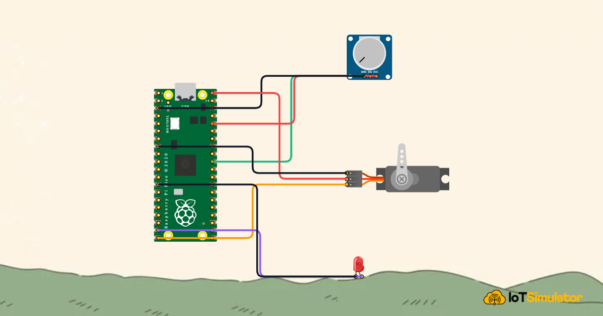
In this project, you will build a servo angle positioner using a Raspberry Pi Pico. By turning a rotary potentiometer knob, you will command an SG90 micro servomotor to rotate smoothly between 0° and 180°. You will also wire an indicator LED that illuminates whenever the motor reaches its mechanical limits, alerting you that the arm cannot turn any further.
How Servomotors Understand Angular Position
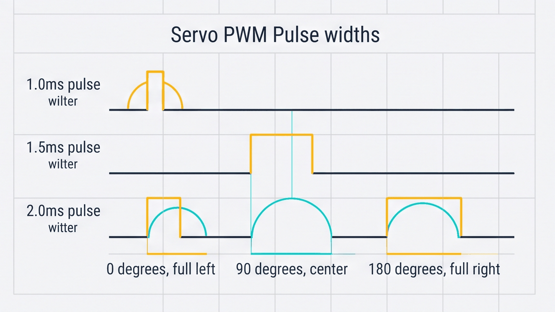
Unlike simple electric motors that change speed based on voltage, a servomotor listens to electrical pulses repeated 50 times every second (a 50 Hz signal with a 20 millisecond period). The width of the high pulse tells an internal controller chip exactly where to hold the motor shaft.
| Pulse Duration | Angular Position | Physical Horn Orientation | Application Example |
|---|---|---|---|
| 1.0 millisecond (1000 µs) | 0° | Far left mechanical stop | Fully closed air vent or left steering limit |
| 1.5 milliseconds (1500 µs) | 90° | Center neutral point | Straight-ahead steering or level camera view |
| 2.0 milliseconds (2000 µs) | 180° | Far right mechanical stop | Fully open air vent or right steering limit |
Inside the servo casing, a small DC motor connects to reduction gears and an internal potentiometer attached to the output shaft. If external weight attempts to nudge the arm out of place, the internal circuitry detects the error and powers the motor to resist the movement, keeping your commanded angle rock solid.
Separating Sensitive Sensors from Motor Power
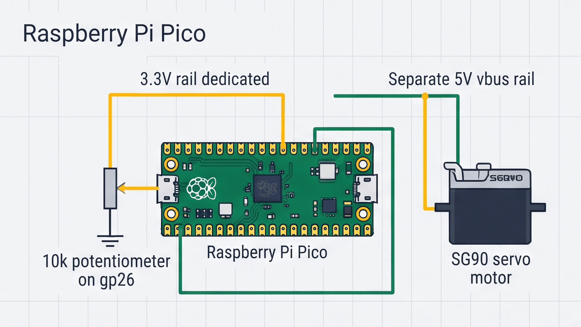
A common mistake when working with motors on the Raspberry Pi Pico is connecting the motor power wire directly to the 3.3V pin. Servomotors contain wire coils that draw sudden bursts of electrical current when starting to move. Drawing that heavy current from the Pico's sensitive 3.3V logic regulator can cause the board to brown out and restart unexpectedly.
| Power Rail | Pico Pin Location | Operating Voltage | Connected Component | Purpose |
|---|---|---|---|---|
| 3.3V Logic Rail | Pin 36 (3V3) | 3.3V Regulated | 10k Potentiometer | Provides a steady, noise-free reference for accurate angle reading |
| 5.0V USB Rail | Pin 40 (VBUS) | 5.0V Raw USB Power | SG90 Micro Servo (Red Wire) | Supplies the heavy current surges needed to move motor gears |
| Common Ground | Pins 13, 18, 38 (GND) | 0V Ground Reference | All Components | Shared return line connecting logic and motor signals |
Connecting motor power directly to VBUS (Pin 40) taps straight into the incoming 5V USB power line, giving the motor plenty of power while keeping the Pico's central processor running smoothly.
Everyday Magic: How Dashboard Needles Work
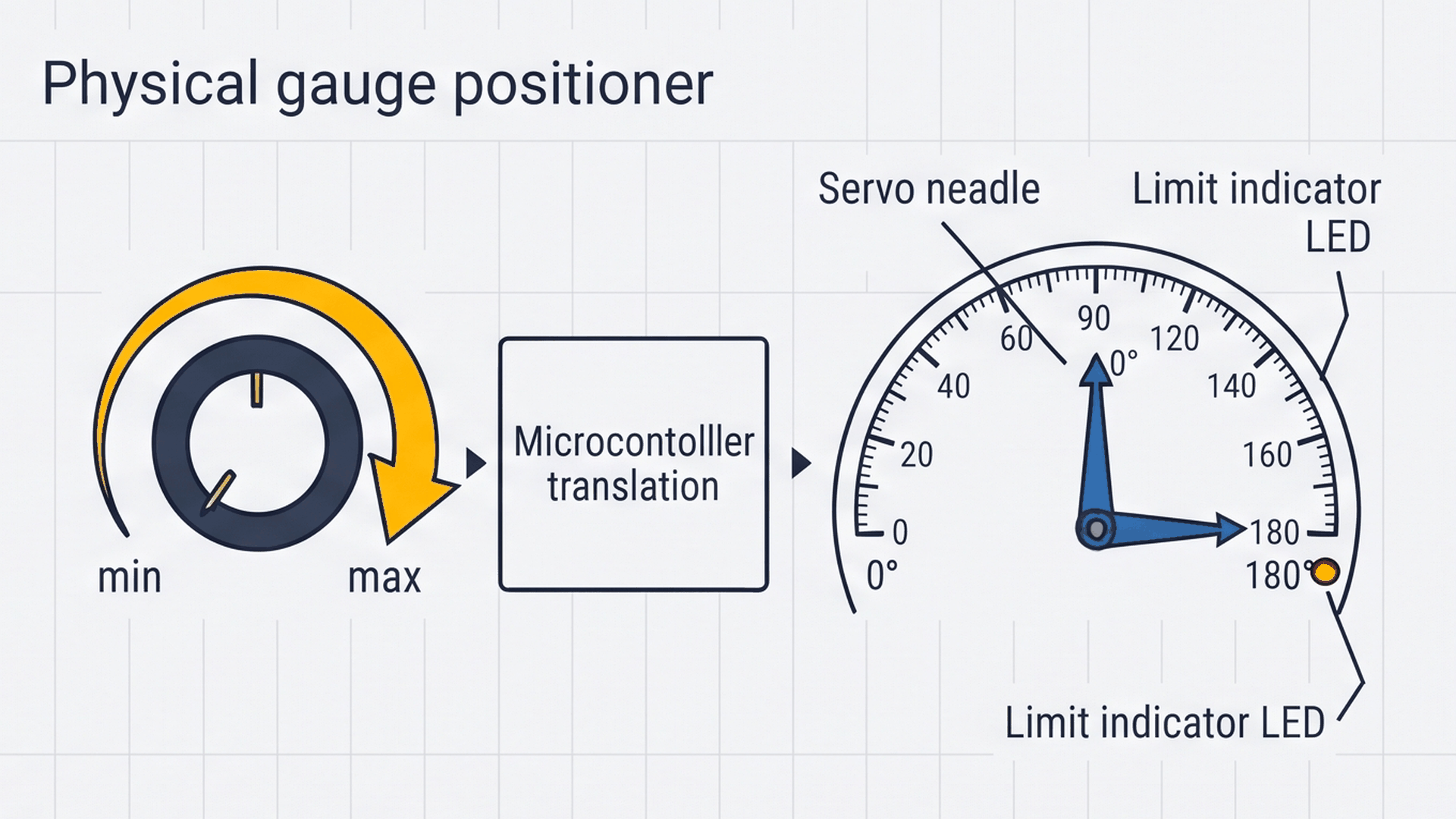
Think of this project like the speedometer needle or fuel gauge on a car dashboard. Instead of a mechanical cable, modern vehicle dials use miniature servo motors. When the engine sensor or fuel float reports a value, the microcontroller calculates the exact angle and sweeps the pointer across the dial face. When it hits the maximum 180-degree mark, an alert LED lights up. The interactive connection tables below show how each module connects to the Raspberry Pi Pico.
Turning the potentiometer knob slides the internal wiper along a resistive track, outputting an analog voltage between 0V and 3.3V that pin GP26 converts into a digital number.
Standard servo ribbon cables follow a color convention: orange is the signal line, red is positive power, and brown (or black) is ground. Confirm each wire aligns with the correct Pico pin before powering on.
The warning LED turns on whenever the commanded angle is within 10 degrees of either mechanical endstop (below 10° or above 170°), visually showing that the motor has reached its physical limit.
Complete Code
Upload the following complete sketch to your Raspberry Pi Pico. Open the Serial Monitor at 115200 baud to view real-time angle updates:
// ============================================================================
// Raspberry Pi Pico Precision Servo Angle Gauge
// Potentiometer Analog Input on GP26 (ADC0)
// Hardware PWM Servo Output on GP15 | Boundary Limit LED on GP14
// ============================================================================

#include <Servo.h>

Servo myServo;
const int POT_PIN   = 26; // Analog ADC0 (Pin 31)
const int SERVO_PIN = 15; // PWM Servo Signal (Pin 20)
const int LED_PIN   = 14; // Limit Alert Indicator (Pin 19)

void setup() {
  Serial.begin(115200);
  delay(200); // USB settling delay

  myServo.attach(SERVO_PIN);
  pinMode(LED_PIN, OUTPUT);

  Serial.println(F("Raspberry Pi Pico Precision Servo Angle Gauge Initialized!"));
}

void loop() {
  // 1. Read 10-bit analog voltage (0 to 1023)
  int potVal = analogRead(POT_PIN);

  // 2. Map analog dial rotation directly to servo angular degrees (0 to 180°)
  int angle = map(potVal, 0, 1023, 0, 180);
  angle = constrain(angle, 0, 180);

  // 3. Command the hardware PWM servo position
  myServo.write(angle);

  // 4. Illuminate warning LED at mechanical endstop boundaries (< 10° or > 170°)
  if (angle <= 10 || angle >= 170) {
    digitalWrite(LED_PIN, HIGH);
  } else {
    digitalWrite(LED_PIN, LOW);
  }

  // 5. Stream telemetry over Serial
  Serial.print(F("[SERVO] ADC: "));
  Serial.print(potVal);
  Serial.print(F(" -> Target Angle: "));
  Serial.print(angle);
  Serial.println(F("°"));

  delay(25); // ~40Hz update rate for smooth physical tracking
}
How the Code Works, Part by Part
The program runs a continuous 40 Hz loop that translates potentiometer movement into motor motion with boundary protection.
Reading the Potentiometer and Mapping to Degrees
The loop begins by reading the potentiometer voltage and scaling it directly into degrees:
int potVal = analogRead(POT_PIN);
int angle = map(potVal, 0, 1023, 0, 180);
angle = constrain(angle, 0, 180);
The map() function translates the 0-1023 analog range into 0-180 degrees. The constrain() call guarantees that electrical noise never tries to push the servo past 180° or below 0°, protecting the mechanical plastic gears inside.
Commanding the Servo Angle
With the target angle calculated, the Servo library sends the appropriate pulse train to pin GP15:
myServo.write(angle);The write() function converts the degree value into the exact microsecond pulse duration needed, pulsing pin GP15 every 20 milliseconds in the background without tying up processor time.
Detecting Mechanical Limits
To let the user know when the dial is near its limits, an if statement checks the angle:
if (angle <= 10 || angle >= 170) {
  digitalWrite(LED_PIN, HIGH);
} else {
  digitalWrite(LED_PIN, LOW);
}
When the motor approaches within 10 degrees of either extreme (0° to 10° or 170° to 180°), pin GP14 lights up the LED. As soon as the knob returns to the safe middle zone, the LED turns off.
Fixing Common Problems
If your servo motor is not responding or behaving erratically, review the troubleshooting table below:
| Observed Problem | Likely Cause | How to Fix |
|---|---|---|
| Pico resets or disconnects when servo moves | Servo power connected to 3.3V instead of VBUS | Move the servo red wire to VBUS (Pin 40), which supplies direct 5V USB power. |
| Servo turns the opposite way when rotating knob | Outer potentiometer legs reversed | Swap the VCC and GND connections on the potentiometer, or change map(potVal, 0, 1023, 180, 0). |
| Servo twitches or vibrates slightly at rest | Slight electrical noise on analog wire | Add a tiny 2-degree deadband check in code so minor sensor flickers are ignored. |
| Servo hums loudly but will not turn | Mechanical arm jammed or bad wire | Check that the servo horn is not physically blocked and verify orange wire is in GP15. |
Remember that standard SG90 servos have physical internal stops preventing 360-degree rotation. Never force the horn with your hands when power is applied.
Try It in the Simulator
Click the Start Simulation button in the top toolbar to begin. Click and drag the potentiometer knob with your mouse: watch the virtual servo horn follow your dial smoothly. Move the dial all the way to the left or right to see the yellow boundary LED illuminate as the angle enters the limit zone.
More in Raspberry Pi Pico
More in PWM
More in Motors
More in Beginner
Build a 4-Key Piano Synthesizer with a Raspberry Pi Pico W
Build a Light Meter and Alarm with a Raspberry Pi Pico
Build a Motion Security Chime with an Arduino Nano
Build an Automatic Night Light with an Arduino Nano