Build a 4-Key Piano Synthesizer with a Raspberry Pi Pico W

Live project track
From electronic stage keyboards and retro 8-bit video game synthesizers to handheld toys, electronic musical instruments work by vibrating air at precise speeds. When an electrical pulse oscillates a tiny speaker cone or ceramic disc hundreds of times every second, your ears perceive that vibration not as random noise, but as a clear musical pitch. Building your own pocket synthesizer is an exciting way to explore how code creates melody.
In this project, you will build a 4-key musical piano synthesizer using a Raspberry Pi Pico W, four tactile pushbuttons, four color-coded LEDs, and a passive piezo buzzer. Pressing any key plays the corresponding musical note (Do, Re, Mi, or Fa) through the buzzer while illuminating that key's matching LED, and releasing the button silences the sound immediately.
Musical Notes and Sound Frequencies
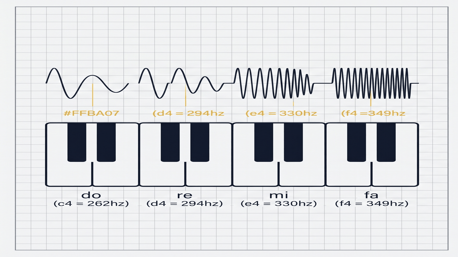
In music acoustics, every musical note has a fundamental pitch measured in Hertz (Hz), which indicates how many times the sound wave completes a full vibration each second. Faster vibrations produce higher-pitched notes, while slower vibrations sound lower in pitch.
| Piano Key | Musical Solfege | Standard Note | Acoustic Frequency | Indicator LED Color |
|---|---|---|---|---|
| Key 1 (GP10) | Do | C4 (Middle C) | 262 Hz | Red LED (GP16) |
| Key 2 (GP11) | Re | D4 | 294 Hz | Yellow LED (GP17) |
| Key 3 (GP12) | Mi | E4 | 330 Hz | Green LED (GP18) |
| Key 4 (GP13) | Fa | F4 | 349 Hz | Blue LED (GP19) |
Our synthesizer stores these four frequencies in a simple array in code. When you press Key 1, the microcontroller tells the buzzer to vibrate 262 times per second, producing the familiar sound of Middle C. Pressing Key 4 increases the frequency to 349 vibrations per second, playing Note F.
Wiring Buttons with Internal Pull-Up Resistors
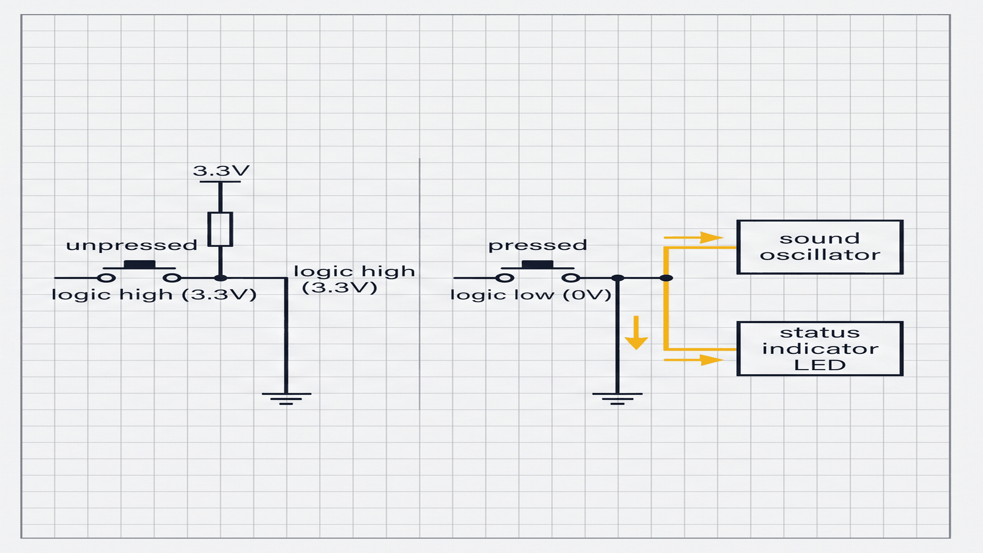
When connecting pushbuttons to a microcontroller, a common hurdle is handling a disconnected or floating pin when the button is released. Without a steady voltage reference, the input wire acts like a tiny antenna that catches random electrical noise, flickering unpredictably between HIGH and LOW.
| Key State | Circuit Path | Voltage at Pico GPIO Pin | Digital Logic Reading | Synthesizer Response |
|---|---|---|---|---|
| Button Released (Idle) | Switch open; internal 50kΩ resistor pulls to 3.3V | 3.3V | HIGH (1) | Silent (LED turns OFF, noTone) |
| Button Pressed (Active) | Switch closed; shorts directly to Ground rail | 0.0V | LOW (0) | Playing (LED turns ON, tone active) |
By declaring pinMode(btnPin, INPUT_PULLUP) in software, the Raspberry Pi Pico W enables an internal 50,000 ohm resistor connected to 3.3V. This guarantees the pin stays at a solid 3.3V (HIGH) until you push the button and connect it to ground. This active-low design saves space on your breadboard by removing the need for external resistors.
Everyday Magic: How 4 Keys Make Music
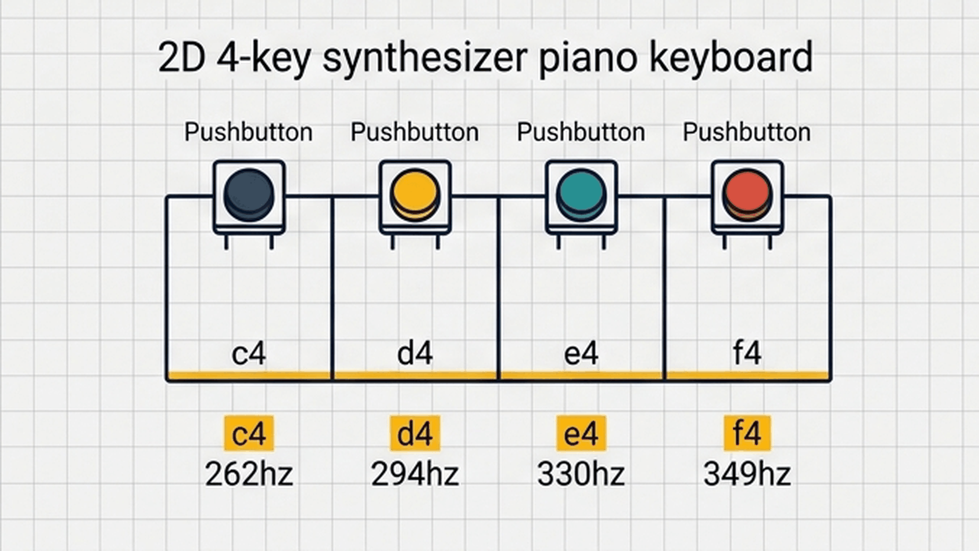
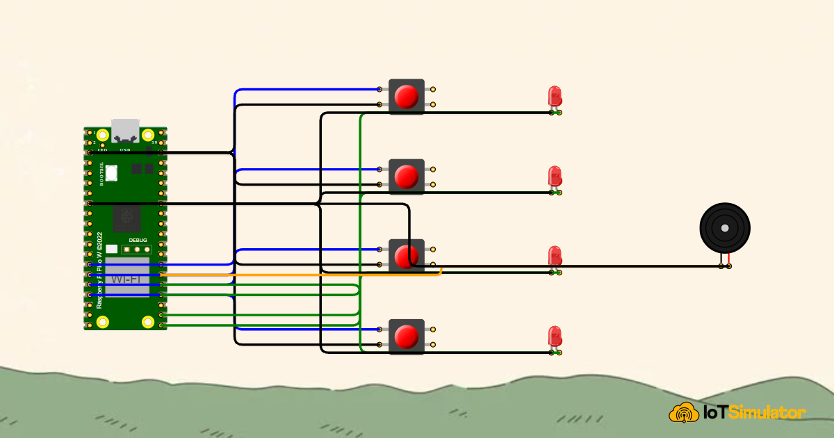
Think of this project like a pocket electronic xylophone or mini synth. Each of the four buttons is assigned to a musical note—Do, Re, Mi, and Fa. When your finger presses a button, the Raspberry Pi Pico W immediately vibrates the piezo speaker at that exact pitch and lights up the corresponding color LED. The interactive connection tables below show how each module connects to the Raspberry Pi Pico W.
Each tactile pushbutton has two sides. Connecting one terminal to its assigned GPIO pin and the other terminal to the ground rail ensures that closing the switch pulls the input to ground.
Always remember that LEDs are polarized: the longer lead is the anode (positive) and connects to the signal pin, while the shorter lead with a flat edge is the cathode (negative) and connects to the ground rail.
A passive piezo buzzer contains a flexible ceramic disc that bends in response to electric signals. When the Pico W toggles pin GP20 at high speeds, this disc flexes back and forth, generating clear audible sound waves.
Complete Code
Upload the following complete sketch to your Raspberry Pi Pico W. As soon as upload completes, you can begin playing musical melodies on the pushbuttons:
// ============================================================================
// Raspberry Pi Pico W 4-Key Tone Piano Synthesizer
// Pushbuttons on GP10, GP11, GP12, GP13 (INPUT_PULLUP)
// Visual LEDs on GP16, GP17, GP18, GP19
// Synthesizer Audio Buzzer on GP20
// ============================================================================

const int btnPins[4] = {10, 11, 12, 13};
const int ledPins[4] = {16, 17, 18, 19};
const int BUZZER_PIN = 20;

// Diatonic Scale Fundamental Frequencies (Hz):
// C4 (Middle Do) = 262 Hz | D4 (Re) = 294 Hz | E4 (Mi) = 330 Hz | F4 (Fa) = 349 Hz
const int noteFrequencies[4] = {262, 294, 330, 349};

void setup() {
  Serial.begin(115200);
  delay(200); // USB settling delay

  for (int i = 0; i < 4; i++) {
    pinMode(btnPins[i], INPUT_PULLUP);
    pinMode(ledPins[i], OUTPUT);
    digitalWrite(ledPins[i], LOW);
  }

  pinMode(BUZZER_PIN, OUTPUT);

  Serial.println(F("Raspberry Pi Pico W 4-Key Tone Synthesizer Initialized!"));
}

void loop() {
  bool isAnyKeyPressed = false;

  for (int i = 0; i < 4; i++) {
    // Check active-low button press (Connecting to GND pulls pin LOW)
    if (digitalRead(btnPins[i]) == LOW) {
      digitalWrite(ledPins[i], HIGH);              // Turn on matching color LED
      tone(BUZZER_PIN, noteFrequencies[i]);        // Play note frequency
      isAnyKeyPressed = true;
    } else {
      digitalWrite(ledPins[i], LOW);               // Turn off LED when key released
    }
  }

  // If no buttons are held down, silence the audio buzzer immediately
  if (!isAnyKeyPressed) {
    noTone(BUZZER_PIN);
  }

  delay(20); // 20ms debounce and scan polling window
}
How the Code Works, Part by Part
The sketch scans all four keys in a loop 50 times per second, managing audio output and visual LED feedback through three simple steps.
Scanning the Piano Keys in a Loop
Rather than writing four separate if statements for each button, a concise for loop iterates through the pin arrays:
for (int i = 0; i < 4; i++) {
  if (digitalRead(btnPins[i]) == LOW) {
    digitalWrite(ledPins[i], HIGH);
    tone(BUZZER_PIN, noteFrequencies[i]);
    isAnyKeyPressed = true;
  } else {
    digitalWrite(ledPins[i], LOW);
  }
}
If button index i is pressed, digitalRead() returns LOW. The program immediately lights that key's matching LED and sets isAnyKeyPressed to true so the system knows a note is currently playing.
Playing Musical Frequencies with Tone
The tone() function generates the acoustic melody by vibrating pin GP20:
tone(BUZZER_PIN, noteFrequencies[i]);The Pico W's hardware timers handle the high-speed switching automatically. When Key 1 is held down, pin GP20 toggles 262 times per second, producing a rich Middle C note without slowing down the rest of your program.
Silencing the Instrument on Release
After checking all four keys, the code evaluates whether any button remains pressed:
if (!isAnyKeyPressed) {
  noTone(BUZZER_PIN);
}
If no keys are currently held down, noTone() turns off the buzzer immediately. This ensures clean, responsive notes that stop the exact millisecond your finger lifts off the key.
Fixing Common Problems
If your synthesizer is not making sounds or behaving as expected, check the troubleshooting table below:
| Observed Problem | Possible Cause | How to Fix |
|---|---|---|
| Buzzer makes a continuous whining sound without pressing buttons | Buttons not configured with pull-ups | Ensure pinMode(btnPins[i], INPUT_PULLUP) is present in setup(). |
| LED turns on when key is pressed, but buzzer stays silent | Active buzzer used instead of passive model | Active buzzers cannot play different musical pitches. Replace with a passive piezo sounder. |
| Notes sound in reverse or scrambled pitch order | Button or LED pin wiring order swapped | Verify Key 1 connects to GP10, Key 2 to GP11, Key 3 to GP12, and Key 4 to GP13 in sequence. |
| Sound clicks or stutters rapidly when holding a button | Loop delay is too short or wire loose | Keep the 20 ms delay at the bottom of loop() to filter out mechanical contact chatter. |
Because passive buzzers are polarized, ensure the side marked with a small '+' sign connects to GP20 and the opposite pin connects to Ground.
Try It in the Simulator
Click the Start Simulation button in the top toolbar to turn on your piano. Click and hold down Key 1 with your mouse to hear Middle C and watch the red LED illuminate. Try pressing the other buttons in sequence—Key 1 (Do), Key 2 (Re), Key 3 (Mi), and Key 4 (Fa)—to play simple musical melodies directly in your browser.