Build an Automatic Night Light with an Arduino Nano

Live project track
Waking up in the middle of the night to pitch-black darkness often leaves you fumbling for light switches, only to be blinded by a harsh ceiling bulb that shocks your eyes and makes falling back asleep difficult. A smart night light solves this problem gently: it stays completely turned off during the bright daytime, but as evening approaches, it gradually illuminates your room with a soft, warm candle-like glow.
In this project, you will build an automatic night light using a compact Arduino Nano V3, a photoresistor light sensor, and an RGB LED. Instead of clicking abruptly between full brightness and pitch darkness, your circuit will smoothly fade its brightness up and down while blending red and green channels to produce a soothing, eye-friendly sunset amber glow.
How Light Sensors Detect Darkness
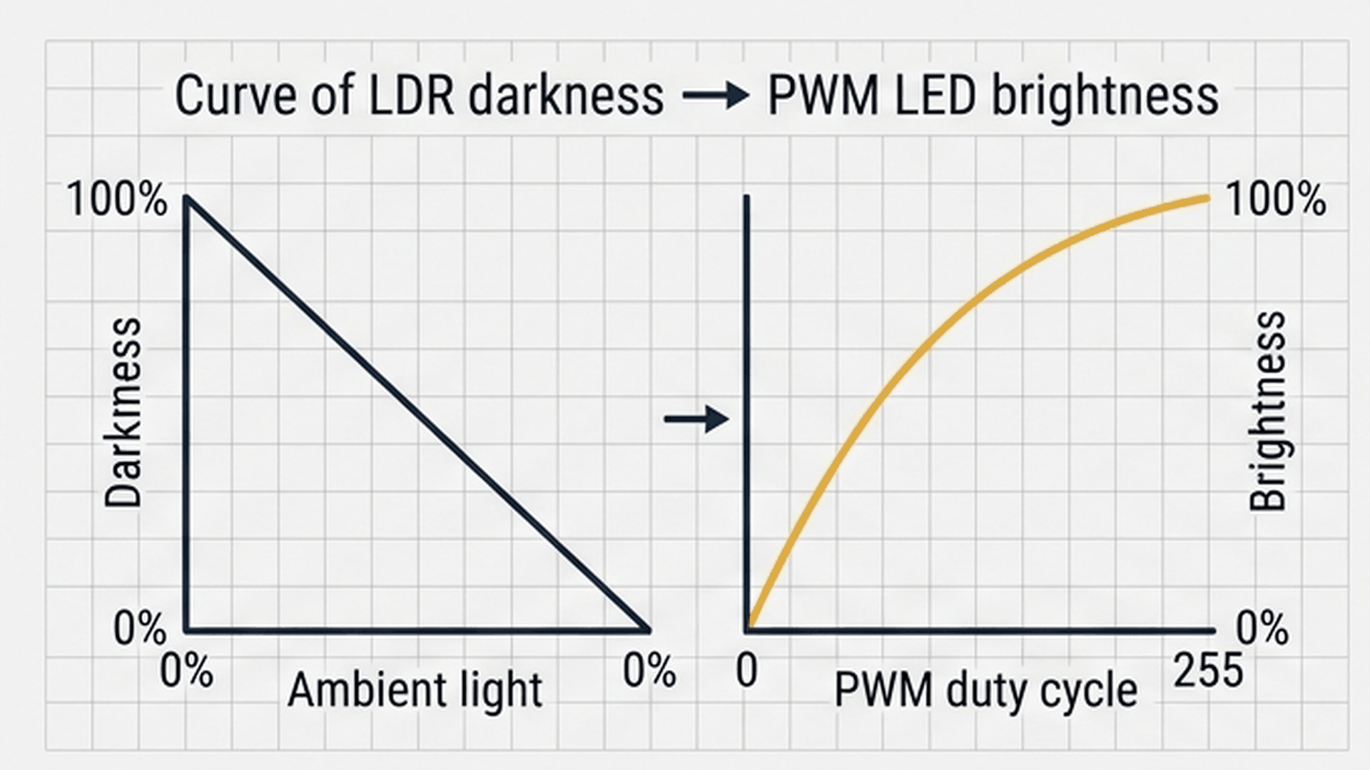
A photoresistor, often called an LDR (Light Dependent Resistor), changes its electrical resistance based on the amount of light falling on its surface. In bright sunlight, its resistance drops dramatically, allowing more current to pass. In darkness, its resistance surges, reducing current flow. When combined with a fixed resistor on a sensor module, this produces an analog voltage that the Arduino Nano reads on pin A0.
| Ambient Condition | Sensor Reading (ADC Pin A0) | Night Light State | LED Brightness (PWM) |
|---|---|---|---|
| Direct Sunlight / Bright Room | 700 to 1023 | Completely OFF | 0 (Conserves energy) |
| Dim Room / Overcast | 400 to 699 | Completely OFF | 0 (Above trigger threshold) |
| Sunset / Twilight | 200 to 399 | Soft Night Glow | 50 to 150 (Gentle amber) |
| Deep Darkness / Night | 0 to 199 | Full Night Glow | 150 to 255 (Clear path lighting) |
By setting a darkness threshold of 400, the Arduino Nano knows exactly when twilight arrives. As room light drops below 400, the microcontroller smoothly scales up the LED brightness. This gradual transition prevents the jarring sudden flash common in cheaper click-on night lights.
Creating Warm Amber Light Without Harsh Glare
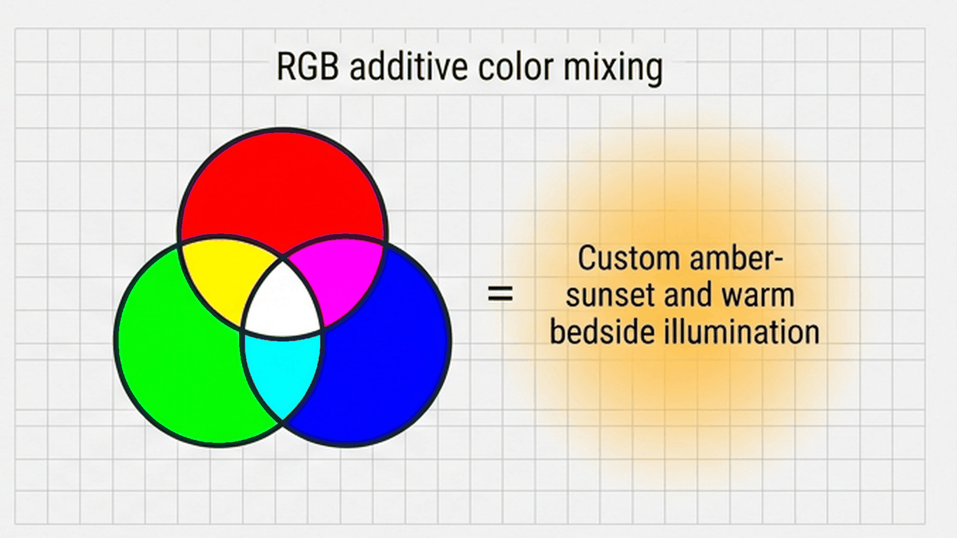
Standard white LEDs often emit strong blue light wavelengths that stimulate daylight receptors in human eyes, telling your brain that it is morning and disrupting natural sleep patterns. To make our night light comfortable for bedrooms and hallways, we use an RGB LED to custom-blend an eye-friendly warm amber glow.
| LED Color Channel | Arduino Nano Pin | PWM Output Ratio | Visual Function |
|---|---|---|---|
| Red Channel | Digital Pin D9 (PWM) | 100% (Full brightness) | Provides warm foundational glow and primary night visibility |
| Green Channel | Digital Pin D10 (PWM) | 33% (brightness / 3) | Softens the deep red into a cozy, golden sunset amber |
| Blue Channel | Digital Pin D11 (PWM) | 0% (Completely OFF) | Prevents harsh glare and avoids disrupting restful sleep cycles |
By driving the green channel at exactly one-third the brightness of the red channel, the LED keeps its warm sunset tone whether it is running at a faint 20% glow during early dusk or full brightness in the middle of the night.
Everyday Magic: How Automatic Night Lights Work
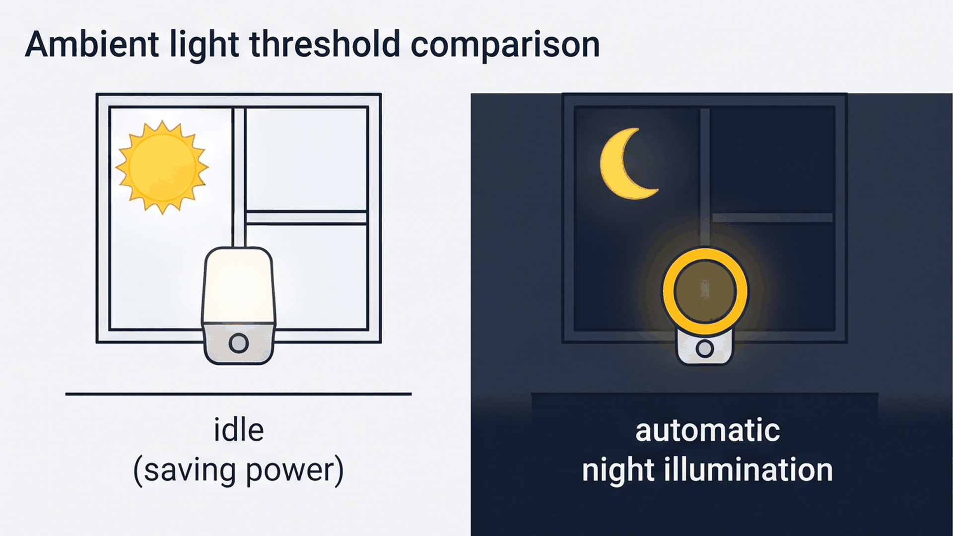
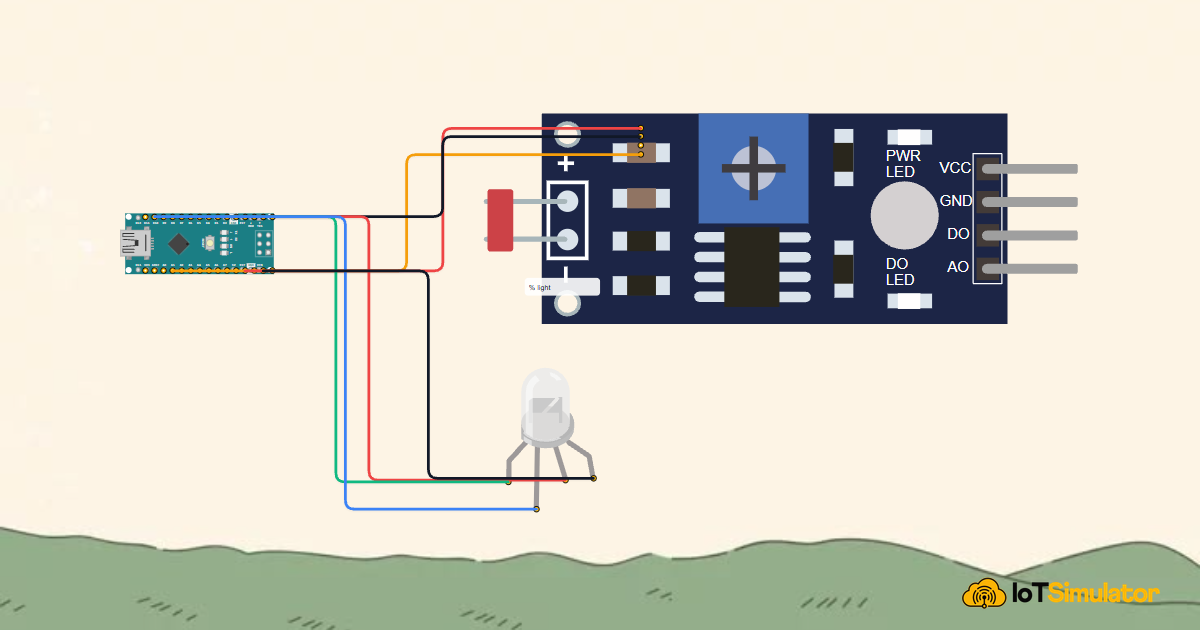
Think of this project like a smart hallway or bedside night light. During the day when the sun is out, the photoresistor detects plenty of light, so the Arduino keeps the LED completely off to save electricity. But as sunset arrives and the room grows dark, the microcontroller smoothly turns on a warm amber glow to keep paths visible. The interactive connection tables below show how each module connects to the Arduino Nano.
The photoresistor module has a built-in voltage divider resistor on board, allowing you to connect its analog output pin directly to analog pin A0 on the Arduino Nano without any extra breadboard resistors.
A common cathode RGB LED has four pins: the longest pin is the cathode, which connects directly to the Nano's ground header. The other three pins are the individual anodes for red, green, and blue. Connecting them to pins D9, D10, and D11 gives us full hardware PWM dimming control.
Complete Code
Here is the complete Arduino sketch for your automatic night light. It reads the ambient light level five times per second and smoothly adjusts the amber glow:
// ============================================================================
// Arduino Nano Automatic Adaptive Night Light
// LDR Sensor on Analog Pin A0
// Common Cathode RGB LED on PWM Pins: Red=9, Green=10, Blue=11
// ============================================================================

const int LDR_PIN   = A0;
const int RED_PIN   = 9;  // Hardware Timer 1 PWM
const int GREEN_PIN = 10; // Hardware Timer 1 PWM
const int BLUE_PIN  = 11; // Hardware Timer 2 PWM

// Threshold below which darkness triggers the night light
const int DARKNESS_THRESHOLD = 400;

void setup() {
  Serial.begin(9600);

  pinMode(RED_PIN, OUTPUT);
  pinMode(GREEN_PIN, OUTPUT);
  pinMode(BLUE_PIN, OUTPUT);

  Serial.println(F("Arduino Nano Automatic Adaptive Night Light Initialized!"));
}

void loop() {
  // 1. Read ambient illumination from Photoresistor (0 to 1023)
  int lightLevel = analogRead(LDR_PIN);

  // 2. Evaluate daylight vs darkness
  if (lightLevel < DARKNESS_THRESHOLD) {
    // Darkness detected: Map light inversely to smooth PWM duty cycle (50 to 255)
    int brightness = map(lightLevel, DARKNESS_THRESHOLD, 0, 50, 255);
    brightness = constrain(brightness, 50, 255);

    // Mix Warm Sunset Amber: Full Red + 1/3 Green + 0 Blue (No harsh blue light)
    analogWrite(RED_PIN, brightness);
    analogWrite(GREEN_PIN, brightness / 3);
    analogWrite(BLUE_PIN, 0);

    Serial.print(F("[NIGHT GLOW] Lux ADC: "));
    Serial.print(lightLevel);
    Serial.print(F(" | Brightness: "));
    Serial.println(brightness);
  } else {
    // Daytime / Room light ON: Completely extinguish LED to conserve energy
    analogWrite(RED_PIN, 0);
    analogWrite(GREEN_PIN, 0);
    analogWrite(BLUE_PIN, 0);

    Serial.print(F("[DAYLIGHT] Lux ADC: "));
    Serial.print(lightLevel);
    Serial.println(F(" | Lamp: OFF"));
  }

  delay(200); // 5Hz sampling cycle
}
How the Code Works, Part by Part
The sketch follows a simple, non-blocking sequence: measuring room illumination, checking if it is dark enough to turn on, calculating proportional brightness, and driving the LED pins.
Reading the Ambient Light Level
Every 200 milliseconds, the loop begins by taking an analog reading from the photoresistor:
int lightLevel = analogRead(LDR_PIN);The Arduino Nano's analog-to-digital converter turns the sensor's voltage into a whole number between 0 (complete darkness) and 1023 (bright direct light).
Smooth Fading with the Map and Constrain Functions
When darkness is detected, the program calculates the target brightness using an inverse mathematical scaling:
int brightness = map(lightLevel, DARKNESS_THRESHOLD, 0, 50, 255);
brightness = constrain(brightness, 50, 255);
The map() function translates our sensor range (400 down to 0) into an output range of 50 up to 255. When the sensor reads 400, brightness is 50. As darkness deepens towards 0, brightness ramps up to 255. The constrain() function ensures the number never exceeds safe 8-bit limits.
Blending Sunset Amber via PWM Pins
Finally, the calculated brightness is distributed across the RGB LED color pins using pulse-width modulation:
analogWrite(RED_PIN, brightness);
analogWrite(GREEN_PIN, brightness / 3);
analogWrite(BLUE_PIN, 0);
Setting the blue pin to 0 ensures zero blue light is emitted. Driving the red channel at full calculated brightness and the green channel at one-third yields the relaxing amber glow that makes this night light so comfortable.
Fixing Common Problems
If your night light is not turning on or showing the right colors, use the table below to quickly find and fix the issue:
| Observed Problem | Likely Cause | Recommended Solution |
|---|---|---|
| LED never illuminates, even in dark | Common cathode pin wired to 5V instead of GND | Ensure the longest leg of the RGB LED connects to a GND header pin on the Arduino Nano. |
| LED glows cyan or magenta instead of amber | Red and green jumper wires swapped | Verify that Pin D9 connects to the Red anode and Pin D10 connects to the Green anode. |
| Lamp flickers rapidly when starting to glow | Optical feedback: LED shines directly onto sensor | Shield the photoresistor so light from the LED does not shine directly into the sensor surface. |
| Serial Monitor displays constant 1023 | Sensor ground wire loose or disconnected | Inspect the black jumper wire connecting the sensor module GND pin to Nano GND.1. |
Opening the Arduino Serial Monitor at 9600 baud allows you to watch the live sensor reading in real time, making it simple to calibrate the threshold for your specific room lighting.
Try It in the Simulator
Click the Start Simulation button in the top toolbar to test your circuit. Click on the photoresistor module to reveal its interactive brightness slider. Drag the slider to the left toward darkness: watch the LED smoothly illuminate and warm up to sunset amber as the reading drops below 400. Drag the slider back to the right to watch the lamp gracefully extinguish.
More in Arduino Nano
More in Sensors
Build a Smart Climate Monitor with a Raspberry Pi Pico W
Build a Light Meter and Alarm with a Raspberry Pi Pico
Build a Multi-Room Safety Monitor with an Arduino Mega
Build a Motion Security Chime with an Arduino Nano
Measure Distance with an ESP32-C3 and Ultrasonic Sensor
More in Lighting
More in PWM
More in Beginner
Build a 4-Key Piano Synthesizer with a Raspberry Pi Pico W
Control a Servo Positioner with a Raspberry Pi Pico
Build a Light Meter and Alarm with a Raspberry Pi Pico
Build a Motion Security Chime with an Arduino Nano