Build a Motion Security Chime with an Arduino Nano

Live project track
Walk into a store, and the moment you cross the doorway, a friendly chime sounds to alert the staff. In home security, that exact same motion-sensing technology powers burglar alarms, catching unexpected intruders before they take another step. Building your own motion-activated security chime lets you explore how sensors detect body heat, how alarm systems switch between armed and disarmed states, and how microcontrollers generate distinctive alert sirens.
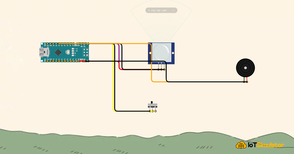
In this project, you will build a motion security chime using an Arduino Nano V3, an HC-SR501 passive infrared (PIR) sensor, a hardware arming slide switch, and a piezo buzzer. When the switch is set to Armed, any movement in front of the sensor immediately triggers a dual-tone warble alarm and logs the alert to the Serial Monitor. When set to Disarmed, the system rests quietly in standby mode.
How Passive Infrared Sensors Detect Movement
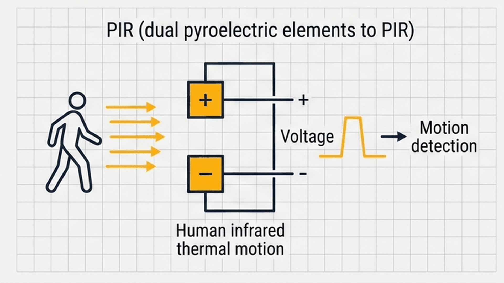
Unlike beam-break sensors that require an emitter shining a beam at a receiver across the room, a Passive Infrared (PIR) sensor does not send out any light or radiation of its own. Instead, it passively listens for infrared heat naturally emitted by warm objects, such as people and pets at roughly 37°C.
| Sensor Stage | Physical Behavior | Electrical Output | Function in Circuit |
|---|---|---|---|
| Fresnel Lens Dome | Focuses ambient infrared heat onto internal sensor slots | Optical refraction | Creates overlapping detection zones across 120° |
| Dual Sensor Elements | Two balanced heat-sensing crystals wired in opposition | Differential voltage (ΔV) | Cancels out room temperature shifts, detecting only moving heat |
| Signal Conditioning | Detects when one slot receives heat before the other | Positive then negative spike | Confirms an object is genuinely moving across the room |
| Digital Output Pin (OUT) | Internal circuit triggers when differential threshold is crossed | Digital HIGH (3.3V) for ~3 seconds | Signals Arduino Nano pin D2 that motion occurred |
Because the two internal crystal elements are wired in reverse polarity, stable room heat strikes both elements equally and cancels out. Only when a person walks across the field of view does one element warm up before the other, generating a voltage swing that pulls the sensor output pin HIGH.
Arming Modes and Siren Patterns
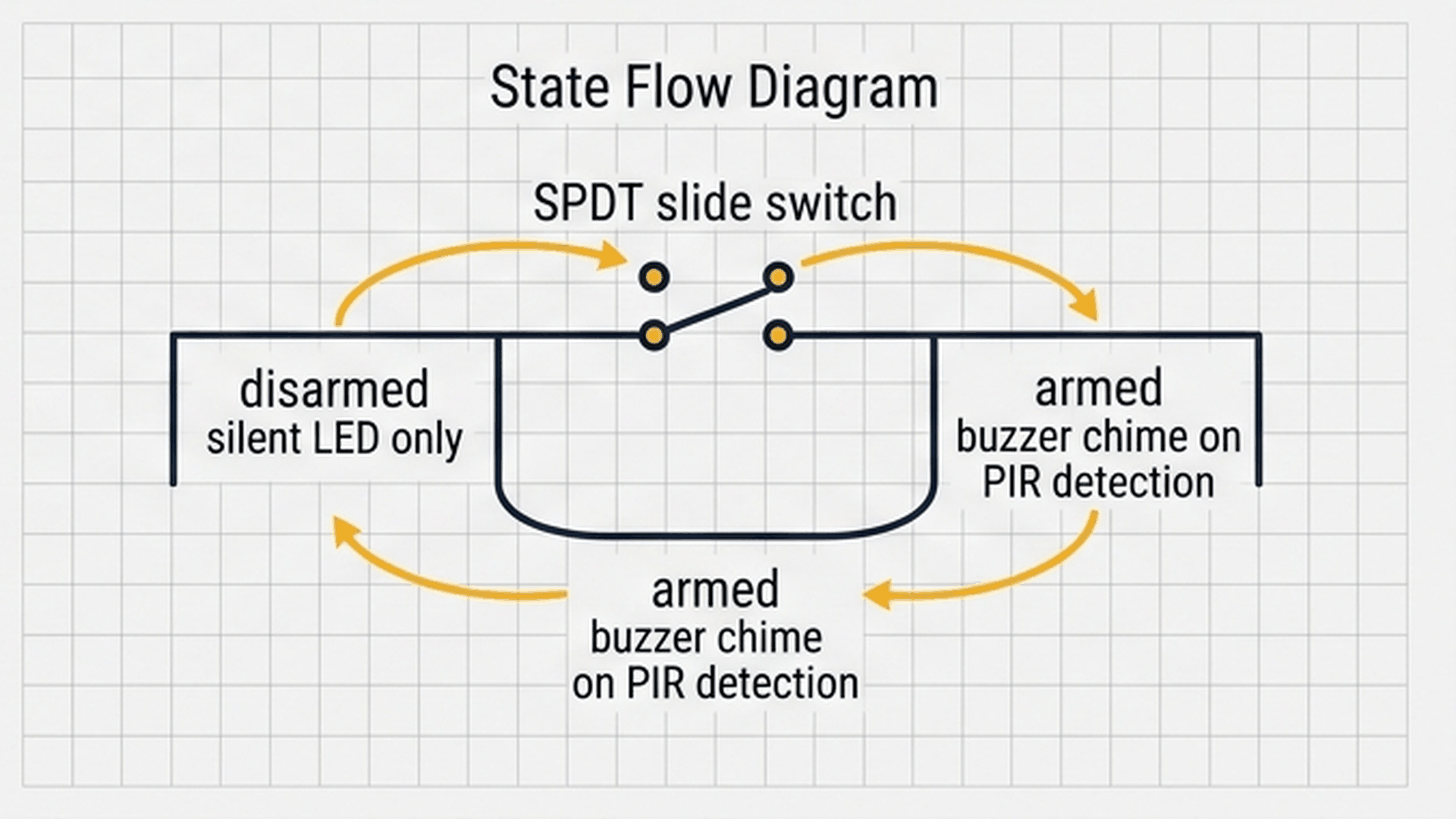
An alarm that sounds every time you walk past your own desk would quickly become frustrating. A slide switch provides physical arming control, allowing you to arm the alarm when leaving the room or disarm it when people are actively using the space.
| System Mode | Slide Switch Position (Pin D3) | Motion Detected Response | Serial Monitor Telemetry |
|---|---|---|---|
| DISARMED (Standby) | Connected to 5V / Open (HIGH) | Ignored; buzzer remains muted | Logs '[STATUS] System STANDBY / DISARMED' every 3 seconds |
| ARMED (Active Guard) | Connected to Ground (LOW) | Triggers dual-tone warble siren | Logs '[STATUS] System ARMED: Area Clear' while waiting |
| BREACH ALERT | Armed + Motion Pin D2 goes HIGH | Plays alternating 1760 Hz and 1318 Hz tones | Logs '[ALERT] Motion Triggered! Perimeter Breach!' |
Rather than playing a flat monotone beep that people easily tune out, the alarm alternates rapidly between musical notes A6 (1760 Hz) and E6 (1318 Hz). This two-tone warble mimics industrial emergency sirens, making it immediately noticeable.
Everyday Magic: How Automatic Door Chimes Work
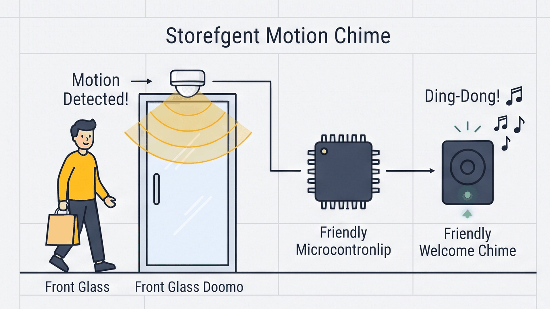
Think of this project like the automatic chime you hear when walking into a local bakery or convenience store. A discreet motion sensor watches the doorway. The instant someone steps across the entrance, the sensor sends a single electrical pulse to the Arduino Nano, which triggers a cheerful two-tone chime to welcome the guest. The interactive connection tables below show how each module connects to the Arduino Nano.
Because pin D3 uses the Arduino Nano's built-in pull-up resistor (INPUT_PULLUP), it stays HIGH until the slide switch flips and connects it directly to ground. This eliminates the need for an external resistor on your breadboard.
A passive piezo buzzer produces different sound pitches depending on the electrical frequency applied to its positive pin. Connecting pin 1 to digital pin D8 allows the Arduino tone() function to generate precise musical frequencies.
Complete Code
Upload the complete sketch below to your Arduino Nano V3. Open the Serial Monitor at 115200 baud to view real-time system logs:
// ============================================================================
// Arduino Nano Motion-Activated Security Chime
// Digital PIR Sensor on Pin D2
// SPDT Arming Switch on Pin D3 (INPUT_PULLUP)
// Piezo Siren Sounder on Pin D8
// ============================================================================

const int PIR_PIN        = 2; // Digital Input (D2) - PIR Motion Sensor
const int ARM_SWITCH_PIN = 3; // Digital Input (D3) - Arming Slide Switch
const int BUZZER_PIN     = 8; // Digital Output (D8) - Piezo Sounder

bool isArmed = false;
bool motionDetected = false;
unsigned long lastLogTime = 0;

void playChimeAlert() {
  // Dual-frequency warble siren pattern (A6 to E6)
  tone(BUZZER_PIN, 1760, 120); // Note A6 (1760 Hz)
  delay(130);
  tone(BUZZER_PIN, 1318, 120); // Note E6 (1318 Hz)
  delay(130);
  tone(BUZZER_PIN, 1760, 150); // Note A6 (1760 Hz)
  delay(160);
  noTone(BUZZER_PIN);
}

void setup() {
  Serial.begin(115200);
  delay(200); // USB settling delay

  pinMode(PIR_PIN, INPUT);
  pinMode(ARM_SWITCH_PIN, INPUT_PULLUP);
  pinMode(BUZZER_PIN, OUTPUT);

  Serial.println(F("Arduino Nano Motion Security Chime Initialized!"));
}

void loop() {
  // Active-LOW slide switch: Connecting D3 to GND arms the system
  isArmed = (digitalRead(ARM_SWITCH_PIN) == LOW);
  motionDetected = (digitalRead(PIR_PIN) == HIGH);

  unsigned long now = millis();

  if (isArmed) {
    if (motionDetected) {
      Serial.println(F("[ALERT] Motion Triggered! Perimeter Breach!"));
      playChimeAlert();
      delay(300); // Cooldown to prevent audio re-trigger spam
    } else if (now - lastLogTime >= 3000) {
      Serial.println(F("[STATUS] System ARMED: Area Clear (Monitoring...)"));
      lastLogTime = now;
    }
  } else {
    if (now - lastLogTime >= 3000) {
      Serial.println(F("[STATUS] System STANDBY / DISARMED"));
      lastLogTime = now;
    }
    noTone(BUZZER_PIN);
    delay(100);
  }
}
How the Code Works, Part by Part
The program coordinates sensor inputs, arming logic, acoustic sound synthesis, and diagnostic reporting through three concise sections.
Reading the Arming Switch and Motion Pin
At the start of every loop iteration, the sketch checks the physical state of the switch and the motion sensor:
isArmed = (digitalRead(ARM_SWITCH_PIN) == LOW);
motionDetected = (digitalRead(PIR_PIN) == HIGH);
Because the switch pin is configured with INPUT_PULLUP, connecting it to ground pulls it LOW, setting isArmed to true. The PIR sensor outputs HIGH whenever moving thermal radiation is detected.
Synthesizing the Dual-Tone Warble Siren
When motion occurs while the system is armed, the playChimeAlert() function executes:
void playChimeAlert() {
  tone(BUZZER_PIN, 1760, 120); // Note A6 (1760 Hz)
  delay(130);
  tone(BUZZER_PIN, 1318, 120); // Note E6 (1318 Hz)
  delay(130);
  tone(BUZZER_PIN, 1760, 150); // Note A6 (1760 Hz)
  delay(160);
  noTone(BUZZER_PIN);
}
By alternating between 1760 Hz and 1318 Hz tones with brief pauses in between, the code creates an energetic acoustic warble. Calling noTone() at the end ensures the buzzer turns completely silent once the melody finishes.
Non-Blocking Status Logging Over Serial
To prevent serial logs from flooding the console every millisecond, the code checks elapsed time using millis():
if (now - lastLogTime >= 3000) {
  Serial.println(F("[STATUS] System ARMED: Area Clear (Monitoring...)"));
  lastLogTime = now;
}
This timer check prints a heartbeat message once every 3 seconds without using delay(), ensuring the microcontroller never misses a sudden motion trigger while waiting.
Fixing Common Problems
If your security chime is behaving unexpectedly, review these common issues and solutions:
| Observed Problem | Possible Cause | Recommended Fix |
|---|---|---|
| Alarm sounds continuously right after powering on | PIR sensor requires warm-up time | HC-SR501 sensors need 30 to 60 seconds after power-up to stabilize their internal crystal temperatures. |
| Alarm triggers even when switch is set to Disarm | Switch wired to wrong contacts | Verify that the center switch pin connects to D3 and the side pin connects to GND. |
| Buzzer makes only a quiet clicking sound | Active buzzer used instead of passive buzzer | Active buzzers only play one fixed pitch. Use a passive piezo sounder that responds to tone() frequency commands. |
| Serial Monitor displays scrambled symbols | Mismatched baud rate setting | Set the Serial Monitor baud rate dropdown in the bottom right corner to 115200 baud. |
Adjusting the sensitivity potentiometer on the edge of the physical HC-SR501 board lets you fine-tune the detection range from 3 meters up to 7 meters to match your room size.
Try It in the Simulator
Click the Start Simulation button in the top toolbar to boot up the system. Flip the slide switch to arm the circuit—you will see the Serial Monitor report '[STATUS] System ARMED'. Click on the PIR sensor and press the Simulate Motion button to watch the alarm trigger, hearing the dual-tone chime and seeing the immediate alert message appear in the console.
More in Arduino Nano
More in Sensors
Build a Smart Climate Monitor with a Raspberry Pi Pico W
Build a Light Meter and Alarm with a Raspberry Pi Pico
Build a Multi-Room Safety Monitor with an Arduino Mega
Build an Automatic Night Light with an Arduino Nano
Measure Distance with an ESP32-C3 and Ultrasonic Sensor
More in Security
More in Audio
More in Beginner
Build a 4-Key Piano Synthesizer with a Raspberry Pi Pico W
Control a Servo Positioner with a Raspberry Pi Pico
Build a Light Meter and Alarm with a Raspberry Pi Pico
Build an Automatic Night Light with an Arduino Nano