Build a Keypad Door Lock with an Arduino Mega

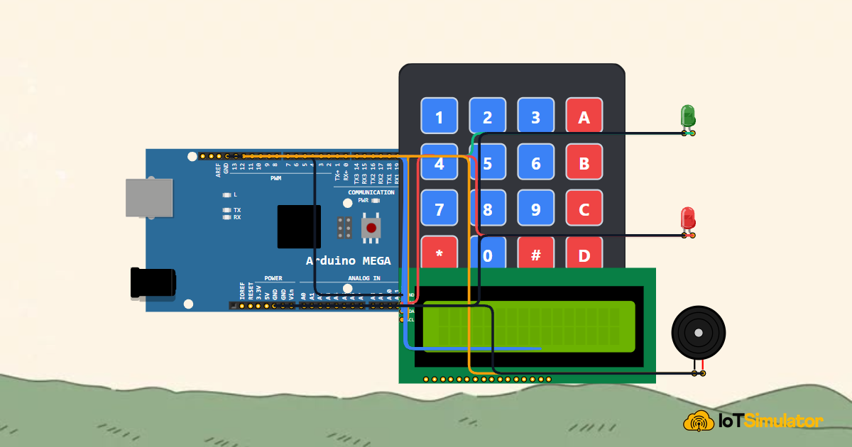
Live project track
From office doors and security safes to electronic gates, numeric keypads are one of the most reliable ways to protect physical spaces. Entering a secret 4-digit code requires active user input, and displaying masked characters such as asterisks (* * * *) prevents onlookers from stealing your passcode over your shoulder. Building your own security lock system teaches you how to coordinate multiple inputs and outputs simultaneously into a responsive, real-time device.
In this project, you will build a complete electronic keypad door lock using an Arduino Mega 2560. You will explore how matrix scanning allows 8 microcontroller pins to read 16 separate buttons, display masked real-time feedback on an I2C LCD1602 screen, and trigger green unlock chimes or red warning buzzers based on the entered passcode.
How Matrix Keypads Scan Buttons with Fewer Pins
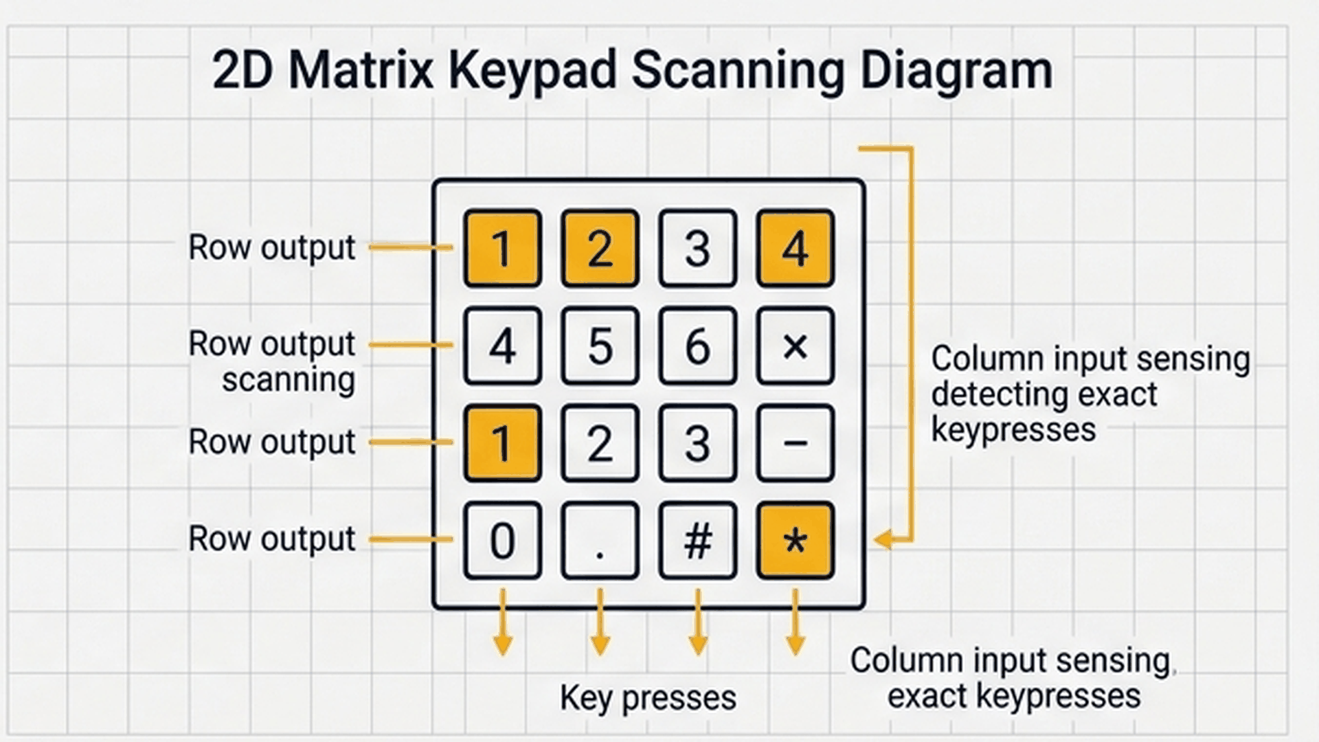
Wiring 16 separate pushbuttons individually to a microcontroller would normally require 16 dedicated digital pins, quickly cluttering your board. A 4x4 matrix keypad solves this challenge by organizing switches into a grid of 4 horizontal row wires and 4 vertical column wires. Pressing a key bridges the electrical contact between one specific row and one specific column.
| Row / Column Pin | Arduino Mega Pin | Pin Mode | Scanning Behavior |
|---|---|---|---|
| Row 1 (R1) | Digital Pin D2 | OUTPUT | Driven LOW during Row 1 scan; HIGH otherwise |
| Row 2 (R2) | Digital Pin D3 | OUTPUT | Driven LOW during Row 2 scan; HIGH otherwise |
| Row 3 (R3) | Digital Pin D4 | OUTPUT | Driven LOW during Row 3 scan; HIGH otherwise |
| Row 4 (R4) | Digital Pin D5 | OUTPUT | Driven LOW during Row 4 scan; HIGH otherwise |
| Column 1 (C1) | Digital Pin D6 | INPUT_PULLUP | Held at 5V by internal pull-up; drops to 0V when key pressed |
| Column 2 (C2) | Digital Pin D7 | INPUT_PULLUP | Held at 5V by internal pull-up; drops to 0V when key pressed |
| Column 3 (C3) | Digital Pin D8 | INPUT_PULLUP | Held at 5V by internal pull-up; drops to 0V when key pressed |
| Column 4 (C4) | Digital Pin D9 | INPUT_PULLUP | Held at 5V by internal pull-up; drops to 0V when key pressed |
The Arduino Mega continuously loops through each row one by one, temporarily pulling it LOW while keeping the other rows HIGH. When a key like '6' is pressed, it connects Row 2 to Column 3, pulling pin D8 to ground. The microcontroller instantly detects this LOW signal and identifies the exact character by matching row and column coordinates.
Handling PIN Verification and Access Feedback
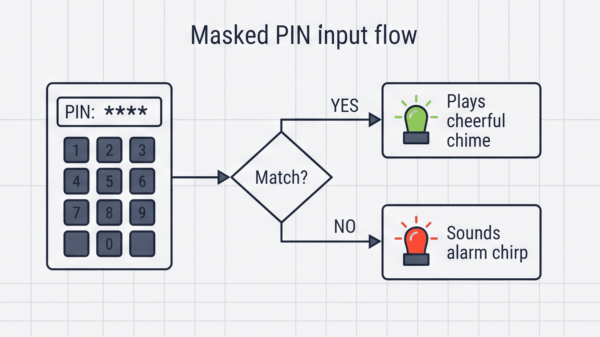
A dependable access terminal must clearly inform the user of what is happening while safeguarding confidential information. When numbers are entered, the system accumulates keystrokes in a temporary memory variable and updates the screen with brackets and asterisks ([* * _ _]). This provides visual confirmation of how many digits have been entered without revealing the secret numbers.
| System State | LCD Display Message | LED Indicator | Buzzer Audio Response |
|---|---|---|---|
| Idle Standby | Enter PIN Code: [_ _ _ _] | Both LEDs OFF | Silent (Ready for interaction) |
| Key Pressed | Updates masked asterisks | Both LEDs OFF | Short click chirp (1500 Hz for 30 ms) |
| Access Granted | ACCESS GRANTED! Door Unlocked | Green LED ON (D11) | Two-tone rising chime (1800 Hz then 2400 Hz) |
| Access Denied | ACCESS DENIED! Invalid Passcode | Red LED ON (D12) | Low warning tone (400 Hz for 500 ms) |
| Buffer Cleared | Resets to [_ _ _ _] | Both LEDs OFF | Short click chirp on '*' key press |
Pressing the '#' key signals that the user has finished entering their passcode and wants to submit it. The firmware compares the entered string against the stored master code '1234'. If they match, the green LED lights up and a two-tone chime sounds. If they do not match, the red LED illuminates, a low alarm tone sounds, and both states hold for a few seconds before returning automatically to standby.
Safe Box Access: Granted vs Denied

Think of this project like a digital bank safe or hotel door lock. The microcontroller stores a secret 4-digit password in memory. Every time a user types four numbers on the keypad, it evaluates whether they match the secret code: a correct PIN instantly unlocks access with a green light and chime, while any wrong entry sounds an alert. The interactive connection tables below show how each module connects to the Arduino Mega.
The membrane keypad ribbon cable connects directly to header pins D2 through D9 on the Arduino Mega. Because we enable the Mega's built-in pull-up resistors in software, you do not need any external pull-up resistors on the breadboard.
On the Arduino Mega 2560, the hardware I2C bus pins are located at digital pins D20 (SDA) and D21 (SCL). Connecting the LCD backpack to these pins leaves all standard general-purpose digital pins free for other devices.
Both LED cathodes and the piezo buzzer negative lead return to the common ground rail (GND.2) on the Mega header. Always observe proper LED polarity: the longer leg (anode) connects to the signal pin, while the shorter flat side (cathode) connects to ground.
Complete Code
The complete Arduino sketch below implements matrix keypad scanning, masked LCD character rendering, and dual-state audio-visual feedback. Upload this code directly to your Arduino Mega 2560:
// ============================================================================
// Arduino Mega Keypad Security Door Lock
// 4x4 Matrix Keypad on Pins 2-9
// I2C LCD1602 on SDA (20) & SCL (21)
// Status LEDs (Pins 11 & 12) and Buzzer (Pin 13)
// ============================================================================

#include <LiquidCrystal_I2C.h>

LiquidCrystal_I2C lcd(0x27, 16, 2);

const int rowPins[4] = {2, 3, 4, 5};
const int colPins[4] = {6, 7, 8, 9};

const char keyMap[4][4] = {
  {'1', '2', '3', 'A'},
  {'4', '5', '6', 'B'},
  {'7', '8', '9', 'C'},
  {'*', '0', '#', 'D'}
};

const int LED_GREEN_PIN = 11;
const int LED_RED_PIN   = 12;
const int BUZZER_PIN    = 13;

// Secret 4-digit Master Passcode
const String MASTER_PIN = "1234";
String enteredPIN = "";

char scanKeypad() {
  for (int r = 0; r < 4; r++) {
    digitalWrite(rowPins[r], LOW);
    for (int c = 0; c < 4; c++) {
      if (digitalRead(colPins[c]) == LOW) {
        delay(20); // Debounce
        while (digitalRead(colPins[c]) == LOW); // Wait for release
        digitalWrite(rowPins[r], HIGH);
        return keyMap[r][c];
      }
    }
    digitalWrite(rowPins[r], HIGH);
  }
  return '\0';
}

void showIdleScreen() {
  enteredPIN = "";
  digitalWrite(LED_GREEN_PIN, LOW);
  digitalWrite(LED_RED_PIN, LOW);
  lcd.clear();
  lcd.setCursor(0, 0);
  lcd.print("Enter PIN Code:");
  lcd.setCursor(0, 1);
  lcd.print("[_ _ _ _]");
}

void setup() {
  for (int r = 0; r < 4; r++) {
    pinMode(rowPins[r], OUTPUT);
    digitalWrite(rowPins[r], HIGH);
  }
  for (int c = 0; c < 4; c++) {
    pinMode(colPins[c], INPUT_PULLUP);
  }

  pinMode(LED_GREEN_PIN, OUTPUT);
  pinMode(LED_RED_PIN, OUTPUT);
  pinMode(BUZZER_PIN, OUTPUT);

  lcd.init();
  lcd.backlight();
  showIdleScreen();
}

void loop() {
  char key = scanKeypad();

  if (key != '\0') {
    tone(BUZZER_PIN, 1500, 30); // Key click chirp

    if (key == '#') { // Submit
      if (enteredPIN == MASTER_PIN) {
        // ACCESS GRANTED
        digitalWrite(LED_GREEN_PIN, HIGH);
        lcd.clear();
        lcd.setCursor(0, 0);
        lcd.print("ACCESS GRANTED!");
        lcd.setCursor(0, 1);
        lcd.print("Door Unlocked");
        tone(BUZZER_PIN, 1800, 200);
        delay(250);
        tone(BUZZER_PIN, 2400, 400);
        delay(2500);
      } else {
        // ACCESS DENIED
        digitalWrite(LED_RED_PIN, HIGH);
        lcd.clear();
        lcd.setCursor(0, 0);
        lcd.print("ACCESS DENIED!");
        lcd.setCursor(0, 1);
        lcd.print("Invalid Passcode");
        tone(BUZZER_PIN, 400, 500);
        delay(2000);
      }
      showIdleScreen();
    } else if (key == '*') { // Clear
      showIdleScreen();
    } else if (enteredPIN.length() < 4) {
      enteredPIN += key;
      lcd.setCursor(0, 1);
      String masked = "[";
      for (int i = 0; i < 4; i++) {
        if (i < enteredPIN.length()) masked += "*";
        else masked += "_";
        if (i < 3) masked += " ";
      }
      masked += "]";
      lcd.print(masked);
    }
  }
}
How the Code Works, Part by Part
The firmware is structured into three clean functional blocks: scanning the keypad grid without external libraries, rendering masked strings on the LCD display, and verifying submitted passcodes against the master code.
Scanning the Matrix Keypad
The scanning routine steps through each row pin, pulls it LOW, and checks all four column inputs for a zero-volt connection:
char scanKeypad() {
  for (int r = 0; r < 4; r++) {
    digitalWrite(rowPins[r], LOW);
    for (int c = 0; c < 4; c++) {
      if (digitalRead(colPins[c]) == LOW) {
        delay(20); // Debounce
        while (digitalRead(colPins[c]) == LOW); // Wait for release
        digitalWrite(rowPins[r], HIGH);
        return keyMap[r][c];
      }
    }
    digitalWrite(rowPins[r], HIGH);
  }
  return '\0';
}
Adding a small 20 millisecond delay eliminates mechanical contact chatter (switch bounce). The while loop waits until the user releases the key before returning the character, guaranteeing that one single physical press registers as exactly one character.
Masking PIN Digits on the LCD Screen
To prevent visual eavesdropping, the program constructs a formatted bracket string with asterisks for entered digits and underscores for remaining slots:
if (enteredPIN.length() < 4) {
  enteredPIN += key;
  lcd.setCursor(0, 1);
  String masked = "[";
  for (int i = 0; i < 4; i++) {
    if (i < enteredPIN.length()) masked += "*";
    else masked += "_";
    if (i < 3) masked += " ";
  }
  masked += "]";
  lcd.print(masked);
}
By setting the cursor directly to line 1 and rewriting the formatted bracket string, the display updates cleanly on every key press without needing a full screen clear, avoiding display flicker.
Validating the Master Code and Triggering Alerts
When the user presses the '#' key, the code evaluates whether the entered string matches the stored master passcode:
if (key == '#') {
  if (enteredPIN == MASTER_PIN) {
    digitalWrite(LED_GREEN_PIN, HIGH);
    lcd.clear();
    lcd.setCursor(0, 0);
    lcd.print("ACCESS GRANTED!");
    lcd.setCursor(0, 1);
    lcd.print("Door Unlocked");
    tone(BUZZER_PIN, 1800, 200);
    delay(250);
    tone(BUZZER_PIN, 2400, 400);
    delay(2500);
  } else {
    digitalWrite(LED_RED_PIN, HIGH);
    lcd.clear();
    lcd.setCursor(0, 0);
    lcd.print("ACCESS DENIED!");
    lcd.setCursor(0, 1);
    lcd.print("Invalid Passcode");
    tone(BUZZER_PIN, 400, 500);
    delay(2000);
  }
  showIdleScreen();
}
If the entered code matches '1234', the green LED illuminates and a two-tone rising chime plays before granting access. If incorrect, the red LED lights up and a low 400 Hz warning tone plays. After a short delay, showIdleScreen() resets the system back to standby.
Fixing Common Problems
If your security lock is not behaving as expected, check the table below for common symptoms and their quick solutions:
| Symptom | Probable Cause | Solution |
|---|---|---|
| LCD screen shows dark blue or black boxes | Contrast potentiometer incorrectly adjusted | Turn the small blue potentiometer on the back of the I2C backpack using a screwdriver until characters appear. |
| LCD screen is completely blank | Incorrect I2C address or wiring | Verify that SDA connects to D20 and SCL connects to D21, and confirm your backpack uses address 0x27 or 0x3F. |
| Keypad registers incorrect letters or numbers | Row and column wire order reversed | Confirm that row pins R1 to R4 connect to D2 through D5, and column pins C1 to C4 connect to D6 through D9 in sequential order. |
| Single key press registers multiple characters | Missing switch debounce or floating pins | Ensure column pins are declared as INPUT_PULLUP in setup() and that the 20 ms debounce delay is present. |
| Buzzer makes no sound on key presses | Reversed buzzer leads or wrong pin assignment | Ensure the buzzer positive pin is wired to D13 and the negative pin connects to GND. |
Testing each peripheral individually—first verifying LCD text, then serial logging keypresses, and finally testing LED and buzzer tones—makes isolating hardware issues straightforward.
Try It in the Simulator
Click the Start Simulation button in the top toolbar to boot up the Arduino Mega. Use your mouse to press keys on the virtual 4x4 keypad. Try typing '1234' followed by '#' to see the screen show ACCESS GRANTED and illuminate the green LED. Then press '*' to clear the buffer, or type an invalid code like '9999' followed by '#' to test the ACCESS DENIED alert.
More in Arduino Mega
More in Security
More in LCD Display
More in Intermediate
Build a Smart Climate Monitor with a Raspberry Pi Pico W
Build a Multi-Room Safety Monitor with an Arduino Mega
Control a Pan and Tilt Servo with an Arduino Mega and Joystick
Read an 8-Bit DIP Switch with an Arduino Mega