Read an 8-Bit DIP Switch with an Arduino Mega

Live project track
At the deepest physical level of modern computer architecture, all data — numbers, text, images, and code instructions — is constructed from 1s and 0s called bits. Eight individual bits grouped together make a single Byte, which can represent any integer value from 0 up to 255.
In this project, you will build an 8-bit digital logic tester using an Arduino Mega 2560, an 8-position DIP switch, and a 10-segment LED bar graph. The main idea is that the Arduino Mega uses its plentiful digital pins to read all eight switches in parallel, combines their states into a single byte using bitwise math, and immediately mirrors the binary pattern onto the LED bar graph and the serial monitor.
How 8 Switches Form a Binary Byte
An 8-position DIP switch contains eight miniature on/off toggle switches inside one small package. Each switch corresponds to one binary digit (bit) in an 8-bit byte. Starting from the right with Bit 0, each position has a numerical value that doubles with every step to the left: 1, 2, 4, 8, 16, 32, 64, and 128.
The diagram above illustrates how the eight switch weights sum together into a final decimal number. In the example shown, switches 0, 1, 4, and 7 are switched on. Adding their values together (1 + 2 + 16 + 128) results in a total decimal value of 147. By toggling different combinations, you can create any number between 0 (all switches off) and 255 (all switches on).
| Bit position | Arduino Mega pin | Binary weight | State when switch is ON |
|---|---|---|---|
| Bit 0 (Least Significant) | Digital Pin D22 | 1 (2⁰) | Adds 1 to byte value |
| Bit 1 | Digital Pin D23 | 2 (2¹) | Adds 2 to byte value |
| Bit 2 | Digital Pin D24 | 4 (2²) | Adds 4 to byte value |
| Bit 3 | Digital Pin D25 | 8 (2³) | Adds 8 to byte value |
| Bit 4 | Digital Pin D26 | 16 (2⁴) | Adds 16 to byte value |
| Bit 5 | Digital Pin D27 | 32 (2⁵) | Adds 32 to byte value |
| Bit 6 | Digital Pin D28 | 64 (2⁶) | Adds 64 to byte value |
| Bit 7 (Most Significant) | Digital Pin D29 | 128 (2⁷) | Adds 128 to byte value |
Because each switch has an exact assigned power of 2, the microcontroller can construct the whole byte using clean bitwise shifting operations in code rather than complex math calculations.
Why We Use Internal Pull-Up Resistors
When you connect a mechanical switch to a microcontroller, a common challenge is what happens when the switch is open. An open switch leaves the microcontroller pin floating in the air, allowing ambient electrical static to make the reading jump unpredictably between 0 and 1.
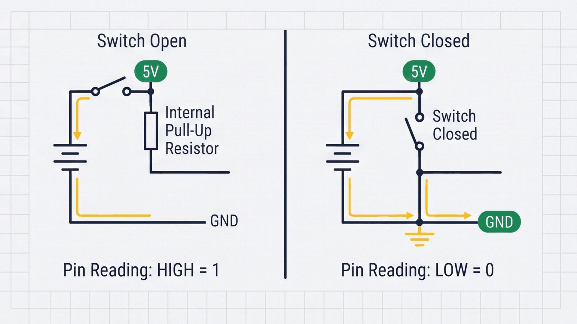
The circuit comparison above explains how the Arduino Mega's built-in INPUT_PULLUP mode solves this without needing eight external resistors. An internal 30kΩ resistor ties the input pin to 5V. When the switch is open (OFF), the pin reads a solid HIGH (5V). When you flip the switch ON, it connects the pin directly to Ground, pulling the voltage down to 0V (LOW).
| Switch position | Physical connection | Voltage at pin | digitalRead() result | Interpreted state |
|---|---|---|---|---|
| Switch OFF (Open) | Connected to 5V via internal pull-up | 5.0 V | HIGH | Bit = 0 (Inactive) |
| Switch ON (Closed) | Connected directly to Ground | 0.0 V | LOW | Bit = 1 (Active) |
Because flipping a switch ON connects it to Ground, this is known as Active-LOW logic: reading LOW means the switch is actively pressed or turned on.
Connecting the Circuit
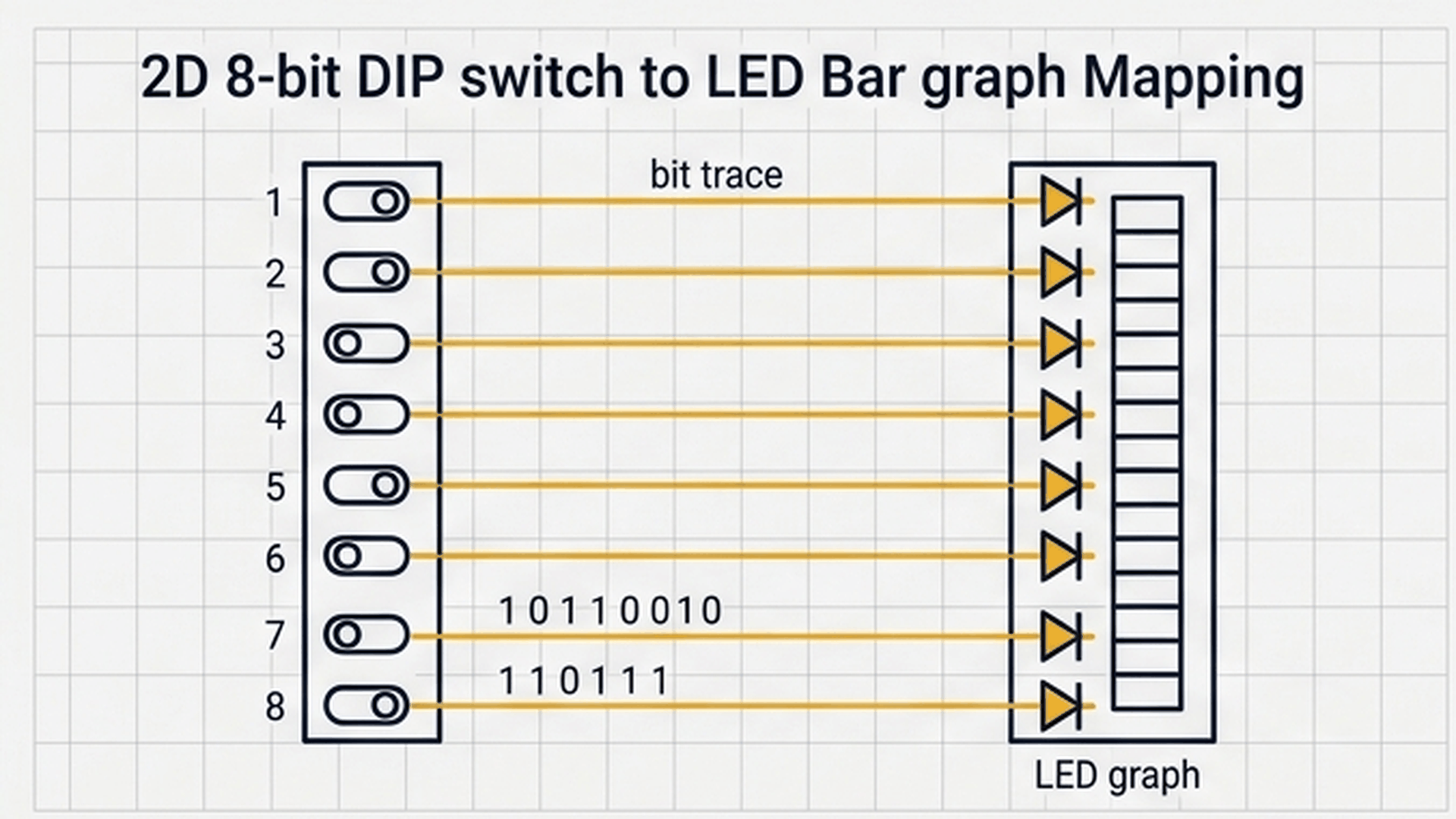
Think of the 8-position DIP switch like a panel of eight mini light switches in a house. When you flip a switch UP, you want its matching light to turn ON immediately. The Arduino Mega reads all 8 switches in parallel and mirrors their state directly to the 8 LEDs.
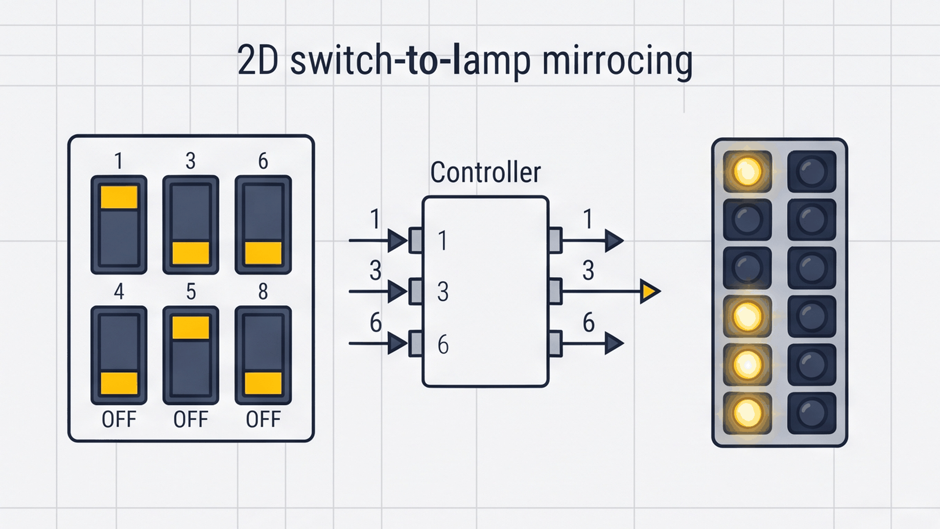
The illustration above shows this direct one-to-one mirroring. When switches 1, 3, and 6 are flipped ON, the Arduino reads those three inputs as active and instantly lights up segments 1, 3, and 6 on the LED bar graph. The interactive pin table below details every terminal connection.
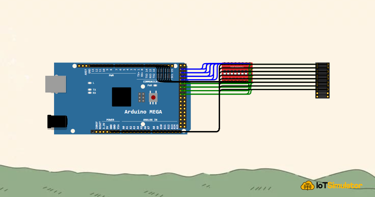
Next, wire the 8 channels of the 10-segment LED bar graph to output pins 22 through 29 through current-limiting resistors to display the switch states:
Notice that we separate the ground rail used for the switches (GND.1) from the ground rail used for the LEDs (GND.2). When all eight LEDs turn on simultaneously, keeping their return current separate from the switch rail prevents voltage fluctuations from interfering with clean switch readings.
Complete Code
Upload the following sketch to your Arduino Mega 2560. It uses pin arrays and compact loops to read all eight switches, mirror them to the LED bar graph, and stream binary and decimal numbers to the Serial Monitor.
// ============================================================================
// Arduino Mega 8-Channel DIP Switch Logic Tester
// Reads 8-bit parallel DIP switch (Pins 22-29) with INPUT_PULLUP
// Mirrors binary state onto 8 segments of an LED Bar Graph (Pins 30-37)
// ============================================================================

const int switchPins[8] = {22, 23, 24, 25, 26, 27, 28, 29};
const int ledPins[8]    = {30, 31, 32, 33, 34, 35, 36, 37};

void setup() {
  Serial.begin(9600);

  // Configure all 8 switch pins as inputs with internal pull-ups
  for (int i = 0; i < 8; i++) {
    pinMode(switchPins[i], INPUT_PULLUP);
    pinMode(ledPins[i], OUTPUT);
    digitalWrite(ledPins[i], LOW);
  }

  Serial.println("Arduino Mega 8-Channel Logic Tester Ready!");
}

void loop() {
  // Build a single 8-bit byte from our 8 switch readings
  byte byteValue = 0;

  // Read each switch position and mirror to corresponding LED
  for (int i = 0; i < 8; i++) {
    // Active LOW: When switch is ON (closed to GND), reading is LOW
    bool isSwitchOn = (digitalRead(switchPins[i]) == LOW);

    if (isSwitchOn) {
      digitalWrite(ledPins[i], HIGH); // Light up corresponding LED segment
      byteValue |= (1 << i);          // Set the i-th bit in our byte
    } else {
      digitalWrite(ledPins[i], LOW);  // Turn off LED segment
    }
  }

  // Print real-time binary byte and decimal value to Serial Monitor
  Serial.print("Binary: ");
  for (int b = 7; b >= 0; b--) {
    Serial.print((byteValue >> b) & 1);
  }
  Serial.print(" | Decimal: ");
  Serial.println(byteValue);

  delay(100); // 100ms refresh rate
}
How the Code Works, Part by Part
The sketch organizes all sixteen physical pins into two clean arrays, allowing the entire system to be managed in short, elegant loops.
▸ Defining Pin Arrays
The top of the sketch creates two integer arrays that store the eight input pins and eight output pins in order.
const int switchPins[8] = {22, 23, 24, 25, 26, 27, 28, 29};
const int ledPins[8]    = {30, 31, 32, 33, 34, 35, 36, 37};
By indexing pins from 0 to 7 in arrays, we can configure and read all sixteen channels in simple for loops rather than writing sixteen separate statements.
▸ Initializing Inputs and Outputs with a Loop
Inside setup(), a single loop configures each switch pin as INPUT_PULLUP and each LED pin as an OUTPUT.
for (int i = 0; i < 8; i++) {
  pinMode(switchPins[i], INPUT_PULLUP);
  pinMode(ledPins[i], OUTPUT);
  digitalWrite(ledPins[i], LOW);
}
Initializing all LED pins to LOW ensures the bar graph starts completely turned off until the first scan cycle runs.
▸ Reading Switches and Building the Byte
Inside loop(), the program resets byteValue to 0 and iterates through all eight switch channels.
bool isSwitchOn = (digitalRead(switchPins[i]) == LOW);

if (isSwitchOn) {
  digitalWrite(ledPins[i], HIGH);
  byteValue |= (1 << i);
} else {
  digitalWrite(ledPins[i], LOW);
}
The bitwise operation byteValue |= (1 << i) shifts a binary 1 into the i-th position of the byte, combining eight individual switch readings into one compact number.
▸ Printing the Binary Number to Serial
To print the 8-bit binary number cleanly from left to right (Bit 7 down to Bit 0), the code uses a countdown loop.
for (int b = 7; b >= 0; b--) {
  Serial.print((byteValue >> b) & 1);
}
Serial.print(" | Decimal: ");
Serial.println(byteValue);
Shifting each bit rightward and masking it with & 1 prints a formatted binary string like 10010011 followed by its decimal equivalent 147.
Fixing Common Problems
If switches appear reversed or the display behaves unexpectedly, check the solutions in the table below.
| What you see | Likely cause | What to try |
|---|---|---|
| LEDs light up when switches are OFF | Logic inverted in comparison | Ensure code checks digitalRead(pin) == LOW for the ON state |
| Bar graph segments light in reverse order | Pin wiring reversed between switch and LEDs | Verify Pin D22 connects to Switch 1 and Pin D30 connects to Bar Graph Segment 1 |
| LEDs flicker randomly when switch is off | Missing pull-up mode on input pins | Verify pins are initialized with INPUT_PULLUP rather than plain INPUT |
| Serial monitor shows unreadable characters | Baud rate setting mismatch | Set the Serial Monitor baud rate dropdown to 9600 baud |
Remember that the LED bar graph is polarized: current must enter through the anodes (A1 to A8) and exit through the cathodes (C1 to C8) to Ground.
Try It in the Simulator
Click the Start Simulation (▶) button in the top toolbar to begin. Click any of the eight rocker switches on the 8-Bit DIP Switch to toggle them on and off. Watch the corresponding green segments on the LED Bar Graph light up instantly, while the Serial Monitor displays the live binary pattern and decimal sum!
More in Arduino Mega
More in Input
More in Intermediate
Build a Smart Climate Monitor with a Raspberry Pi Pico W
Build a Multi-Room Safety Monitor with an Arduino Mega
Build a Keypad Door Lock with an Arduino Mega
Control a Pan and Tilt Servo with an Arduino Mega and Joystick