Build a Light Meter and Alarm with a Raspberry Pi Pico

Live project track
Have you ever wondered how your smartphone screen automatically dims in a dark bedroom and brightens when you step out into the noon sun? Modern gadgets rely on light sensors to measure environmental brightness in real time. In automated security systems, that same sensing principle detects when someone walks past a doorway or blocks an optical beam, sounding an immediate alert the instant shadows fall.
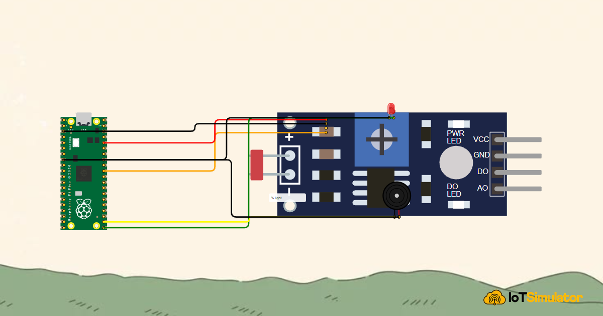
In this project, you will build an ambient light meter and shadow alarm using a Raspberry Pi Pico. You will wire a photoresistor light sensor to analog input pin GP26, convert raw electrical readings into a human-friendly 0% to 100% illumination percentage, and sound a piezo alarm chirp while lighting up an indicator LED whenever the light level falls below 20%.
How the Raspberry Pi Pico Reads Light Levels
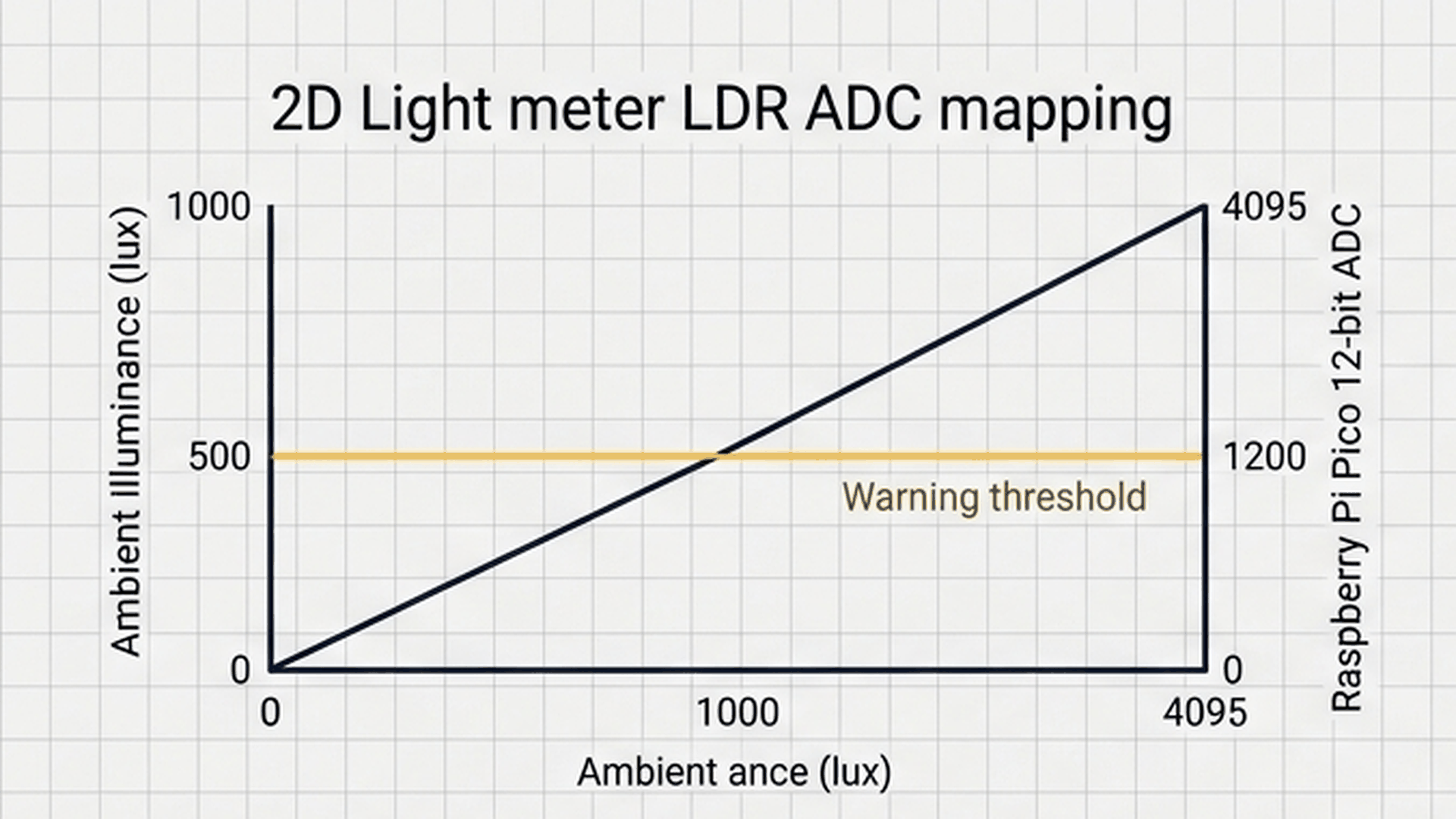
Microcontrollers cannot read brightness directly; they measure electrical voltages between 0V and their power supply voltage (3.3V on the Raspberry Pi Pico). The RP2040 chip on the Pico features an internal Analog-to-Digital Converter (ADC) that translates this continuous voltage into a whole number between 0 and 1023.
| Lighting Environment | Raw ADC Reading (0 - 1023) | Measured Voltage (3.3V Scale) | Calculated Illumination (%) | System Action |
|---|---|---|---|---|
| Direct Sunlight / Bright Lamp | 800 to 1023 | 2.6V to 3.3V | 78% to 100% | Quiet Standby: LED OFF, Buzzer Silent |
| Typical Indoor Room Light | 400 to 799 | 1.3V to 2.5V | 39% to 77% | Quiet Standby: Normal illumination |
| Dim Twilight / Heavy Shadows | 205 to 399 | 0.7V to 1.2V | 20% to 38% | Quiet Standby: Approaching alert threshold |
| Total Darkness / Blocked Sensor | 0 to 204 | 0.0V to 0.6V | 0% to 19% | ALERT ACTIVE: LED turns ON + 1.5 kHz chirp |
By converting the raw 10-bit integer count into a percentage, your code transforms technical numbers into an intuitive metric. When the illumination drops below 20%, the Pico identifies that someone has blocked the light source and triggers an alert.
The Voltage Divider Behind the Sensor
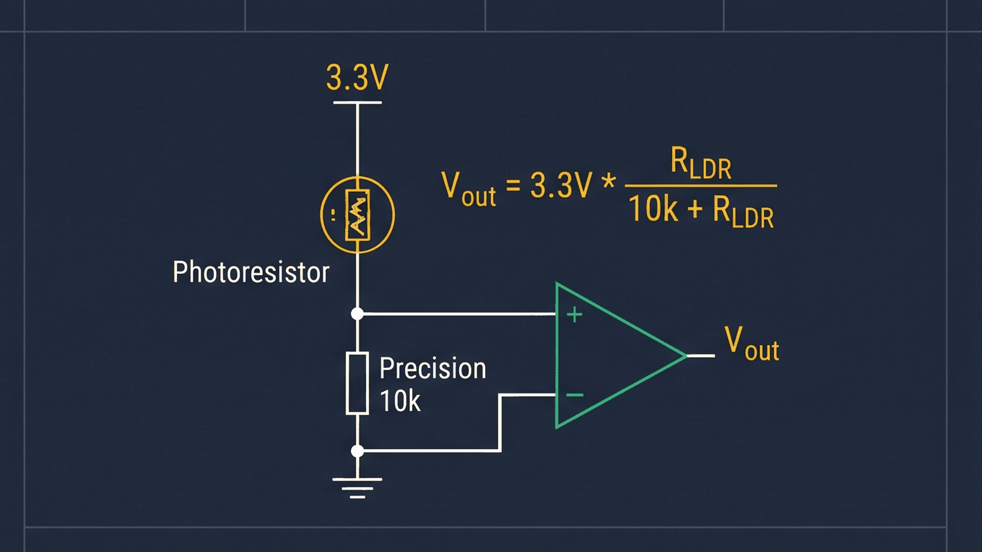
A photoresistor (LDR) alters its electrical resistance in response to incoming light. In bright conditions, its internal resistance drops down to just a few hundred ohms. In total darkness, its resistance surges past 100,000 ohms. Because microcontrollers detect voltages rather than raw ohms, the sensor module places a fixed 10,000 ohm resistor in series with the LDR to form a voltage divider.
| Lighting State | LDR Resistance | Fixed Resistor Share | Midpoint Voltage on Pin GP26 |
|---|---|---|---|
| Bright Sunlight | Drops very low (~500 Ω) | Takes majority of voltage drop | Rises close to 3.3V (~3.14V) |
| Medium Room Light | Moderate (~10,000 Ω) | Evenly divided with fixed resistor | Hovers around midpoint (~1.65V) |
| Deep Shadow / Darkness | Soars very high (> 100,000 Ω) | LDR dominates the resistance chain | Drops close to ground (< 0.50V) |
Because the sensor module already incorporates this reference resistor on its printed circuit board, you can connect the module output directly to the Raspberry Pi Pico without needing any loose resistors on your breadboard.
Everyday Magic: Sunny Rooms vs Dark Closets
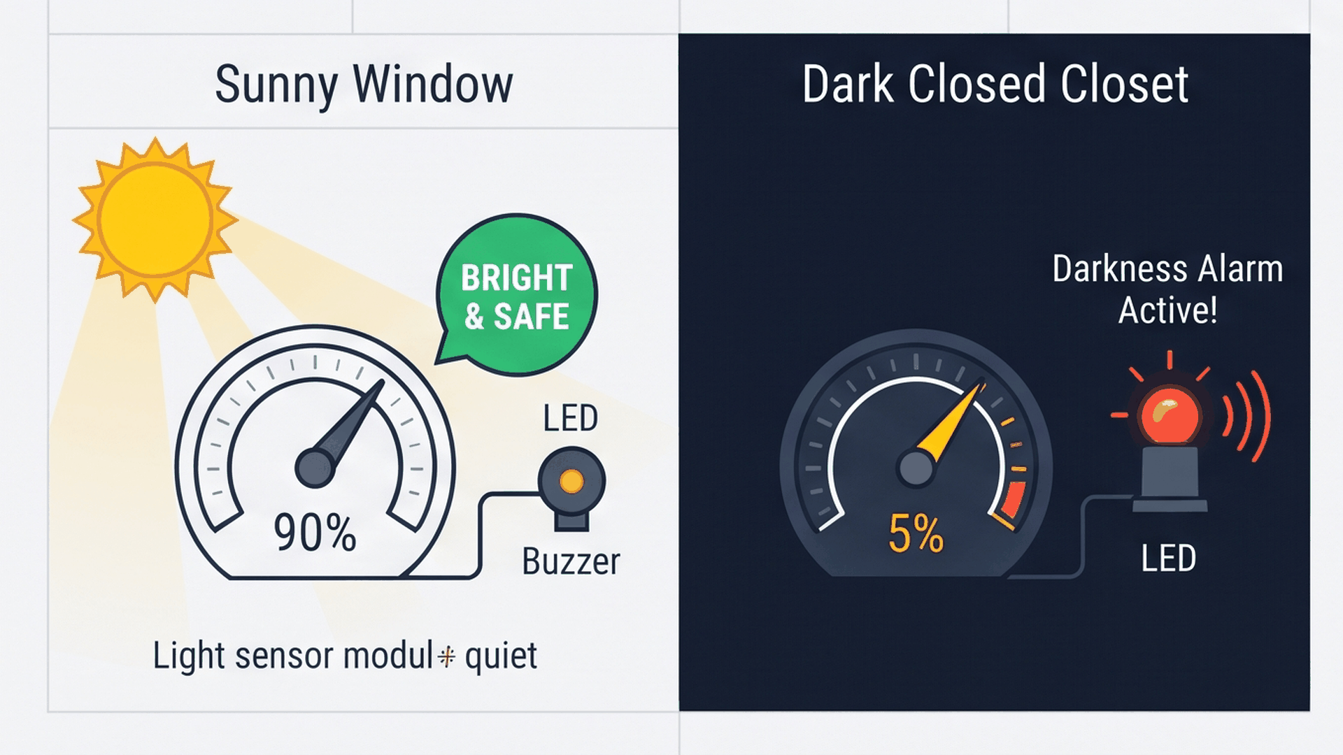
Think of this project like an automated darkness sentinel for a dark storage closet, greenhouse, or museum exhibit. When exposed to normal ambient daylight, the Raspberry Pi Pico measures high illumination and keeps indicators quiet. The moment lights shut off or an object blocks the window, the brightness drops below the safety threshold, sounding the alert. The interactive connection tables below show how each module connects to the Raspberry Pi Pico.
Unlike 5V Arduino boards, the Raspberry Pi Pico operates on a 3.3V logic level. Connecting sensor VCC to the Pico's 3V3 output pin guarantees that the analog signal never exceeds the safe voltage range of the RP2040 chip.
The warning LED and piezo sounder have their own separate ground pins on the Pico header, keeping high-frequency audio switching noise away from the sensitive analog measurement pin.
Complete Code
Here is the complete sketch for your Raspberry Pi Pico light meter. Upload this program to your board and open the Serial Monitor at 115200 baud to observe real-time telemetry:
// ============================================================================
// Raspberry Pi Pico Ambient Light Meter & Occlusion Alarm
// LDR Analog on GP26 (ADC0)
// Status LED on GP16 | Warning Buzzer on GP17
// ============================================================================

const int LDR_PIN    = 26; // Analog ADC0 (Pin 31)
const int LED_PIN    = 16; // Digital Output (Pin 21)
const int BUZZER_PIN = 17; // Digital Tone Output (Pin 22)

// Darkness threshold in percentage (0% = Pitch Black, 100% = Direct Sunlight)
const int OCCLUSION_THRESHOLD_PERCENT = 20;

void setup() {
  Serial.begin(115200);
  delay(200); // USB-CDC settling time

  pinMode(LED_PIN, OUTPUT);
  pinMode(BUZZER_PIN, OUTPUT);

  Serial.println(F("Raspberry Pi Pico Ambient Light Telemetry Hub Initialized!"));
}

void loop() {
  // 1. Sample the analog voltage on GP26 (ADC0)
  int rawADC = analogRead(LDR_PIN);

  // 2. Convert ADC count to continuous voltage (3.3V reference)
  float voltage = rawADC * (3.3f / 1023.0f);

  // 3. Map analog reading into human-readable 0 - 100% illumination
  int luxPercent = map(rawADC, 0, 1023, 0, 100);
  luxPercent = constrain(luxPercent, 0, 100);

  // 4. Stream real-time telemetry over Serial
  Serial.print(F("[LIGHT TELEMETRY] ADC: "));
  Serial.print(rawADC);
  Serial.print(F(" | Voltage: "));
  Serial.print(voltage, 2);
  Serial.print(F("V | Illumination: "));
  Serial.print(luxPercent);
  Serial.println(F("%"));

  // 5. Evaluate darkness / occlusion alarm threshold
  if (luxPercent < OCCLUSION_THRESHOLD_PERCENT) {
    // Sudden darkness or physical sensor occlusion detected!
    digitalWrite(LED_PIN, HIGH);
    tone(BUZZER_PIN, 1500, 80); // 1.5kHz alert chirp
  } else {
    // Normal ambient light conditions
    digitalWrite(LED_PIN, LOW);
    noTone(BUZZER_PIN);
  }

  delay(200); // 5Hz sampling cycle
}
How the Code Works, Part by Part
The sketch executes a 5 Hz measurement cycle that samples the sensor, converts numbers into meaningful engineering units, logs data over USB serial, and checks the alert threshold.
Sampling the Analog Voltage on GP26
At the start of every loop pass, the code takes an analog reading and calculates the real-world voltage:
int rawADC = analogRead(LDR_PIN);
float voltage = rawADC * (3.3f / 1023.0f);
Multiplying the raw reading by 3.3 and dividing by 1023 reconstructs the actual voltage at the sensor pin. This allows you to verify your circuit with a handheld multimeter if troubleshooting is ever needed.
Scaling Into a Percentage
Next, the map and constrain functions turn the integer count into a clean percentage:
int luxPercent = map(rawADC, 0, 1023, 0, 100);
luxPercent = constrain(luxPercent, 0, 100);
The map() function scales the 0-1023 integer range into a 0-100 scale. Calling constrain() ensures that minor electrical fluctuations near the boundaries never result in negative percentages or values above 100%.
Sounding the Occlusion Warning
The final stage compares the calculated percentage against our safety threshold:
if (luxPercent < OCCLUSION_THRESHOLD_PERCENT) {
  digitalWrite(LED_PIN, HIGH);
  tone(BUZZER_PIN, 1500, 80); // 1.5kHz alert chirp
} else {
  digitalWrite(LED_PIN, LOW);
  noTone(BUZZER_PIN);
}
If illumination falls below 20%, pin GP16 powers the LED and tone() plays a crisp 1500 Hz chirp for 80 milliseconds. When bright light returns, the LED turns off and noTone() silences the buzzer.
Fixing Common Problems
If your light meter is not reading light or sounding alarms properly, check the troubleshooting table below:
| Problem | Probable Reason | Solution |
|---|---|---|
| Illumination percentage stays stuck at 0% or 100% | Sensor connected to digital DO pin instead of analog AO | Move the signal jumper wire from DO to the AO (Analog Output) pin on the sensor module. |
| Serial Monitor displays blank screen | Serial terminal opened before USB initialization | Ensure your Serial Monitor is configured to 115200 baud and restart the simulation. |
| Buzzer makes no sound when covered | Buzzer wired to incorrect pin or using active model | Verify that the positive buzzer wire is connected to GP17 and ensure you are using a passive piezo sounder. |
| Alarm triggers randomly in normal room light | Threshold percentage set too high for room lighting | Lower OCCLUSION_THRESHOLD_PERCENT in the code from 20 to 10 to adjust for darker rooms. |
Watching the live voltage readings printed to the Serial Monitor makes calibrating the threshold for any specific room lighting condition fast and accurate.
Try It in the Simulator
Click the Start Simulation button in the top toolbar. Open the Serial Monitor console at the bottom of the screen to watch live telemetry streaming at 5 updates per second. Click on the photoresistor module and slide the brightness slider down below 20%: watch the warning LED turn on and hear the alarm chirp sound until you slide the brightness back up.
More in Raspberry Pi Pico
More in Sensors
Build a Smart Climate Monitor with a Raspberry Pi Pico W
Build a Multi-Room Safety Monitor with an Arduino Mega
Build a Motion Security Chime with an Arduino Nano
Build an Automatic Night Light with an Arduino Nano
Measure Distance with an ESP32-C3 and Ultrasonic Sensor
More in ADC
More in Security
More in Beginner
Build a 4-Key Piano Synthesizer with a Raspberry Pi Pico W
Control a Servo Positioner with a Raspberry Pi Pico
Build a Motion Security Chime with an Arduino Nano
Build an Automatic Night Light with an Arduino Nano