Send an SOS Signal with an ATtiny85 and a Buzzer

Live project track
SOS is the most recognized distress signal in the world. It is transmitted as three short flashes, three long flashes, and three short flashes again — and it does not matter whether you use light, sound, or radio. The rhythm is what carries the message. In this project, pressing a button turns your ATtiny85 into a pocket-sized SOS transmitter: a red LED flashes the pattern while a buzzer beeps it out loud at the same time.
In this project, you will use an ATtiny85 microcontroller, a push button, a red LED, and a piezo buzzer. The main idea is simple: Morse code is just timing. A short signal is called a dot, a long signal is called a dash, and different letters are spelled out by different combinations of dots and dashes. The letter S is three dots, O is three dashes, and your code controls how long each signal lasts.
How Morse Code Timing Works
Every Morse signal is built from one base unit of time — called T. In this project, one unit T equals 150 milliseconds, which is about the time it takes to blink once. A dot lasts exactly 1T (150 ms). A dash lasts exactly 3T (450 ms). Between signals inside the same letter, there is a 1T gap of silence. Between letters, the gap grows to 3T. Between full repetitions of the word SOS, you wait 7T before starting again.
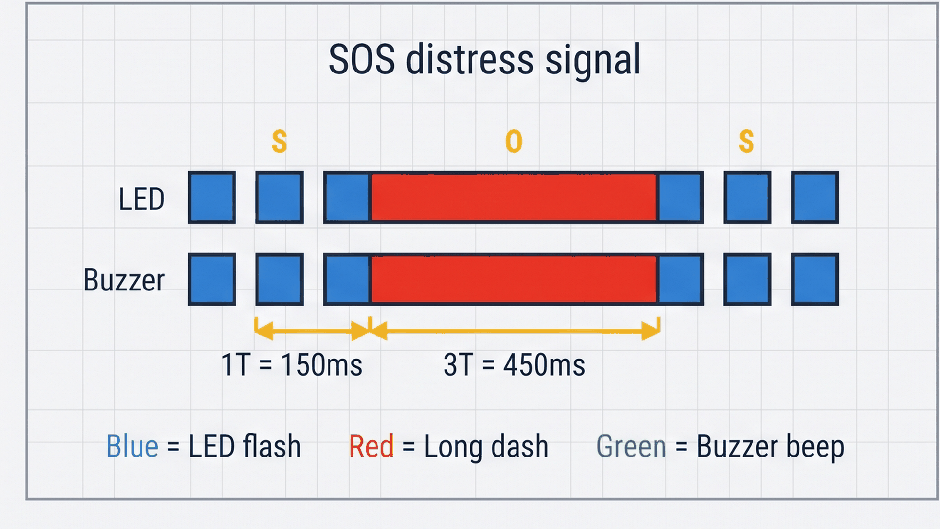
The diagram above shows the full SOS pattern as a timeline. The three short blue blocks are the S dots (150 ms each), the three long red blocks are the O dashes (450 ms each), and then three short blue blocks repeat for the final S. Every block represents both the LED flash and the buzzer beep happening at exactly the same moment. Keeping the timing consistent is what makes the pattern recognizable.
| Signal | Duration | What it means |
|---|---|---|
| Dot (·) | 150 ms (1T) | One short beep and flash |
| Dash (—) | 450 ms (3T) | One long beep and flash |
| Gap inside a letter | 150 ms (1T) | Silence between signals |
| Gap between letters | 450 ms (3T) | Pause between S and O |
| Gap between repetitions | 1050 ms (7T) | Wait before SOS repeats |
You do not need to memorize these numbers — your code handles them automatically using a single constant called DOT. Every other duration is just a multiple of DOT, so changing one number adjusts the entire speed of the signal.
How the LED and Buzzer Work Together
The ATtiny85 drives two output devices at the same time. On pin PB0 (physical pin 5), it switches the red LED on and off with digitalWrite(). On pin PB1 (physical pin 6), it runs the piezo buzzer using tone(), which makes the pin switch HIGH and LOW 1000 times every second. That rapid switching creates a pressure wave in the air that your ear hears as a 1 kHz beep.
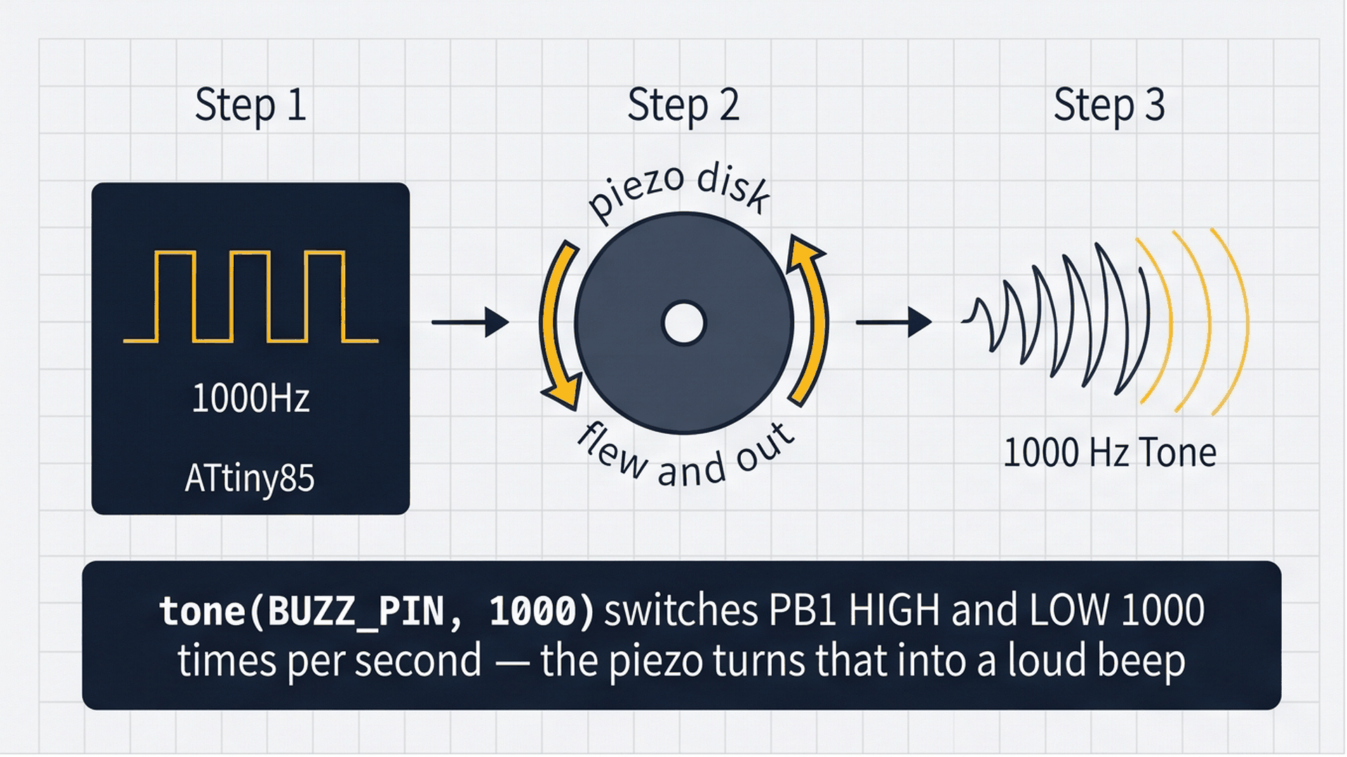
The piezo buzzer contains a small ceramic disk. When voltage is applied, the disk bends slightly. When voltage is removed, it snaps back. Doing this 1000 times per second causes the disk to vibrate, pushing and pulling on the air around it and creating a sound wave. The ATtiny85 does this automatically with just one function call: tone(BUZZ_PIN, 1000). Calling noTone(BUZZ_PIN) stops the vibration instantly.
Both outputs — the LED and the buzzer — are turned on together at the start of each dot or dash, then turned off together at the end. This keeps the visual and acoustic signals perfectly synchronized throughout the entire SOS pattern.
Connecting the Components
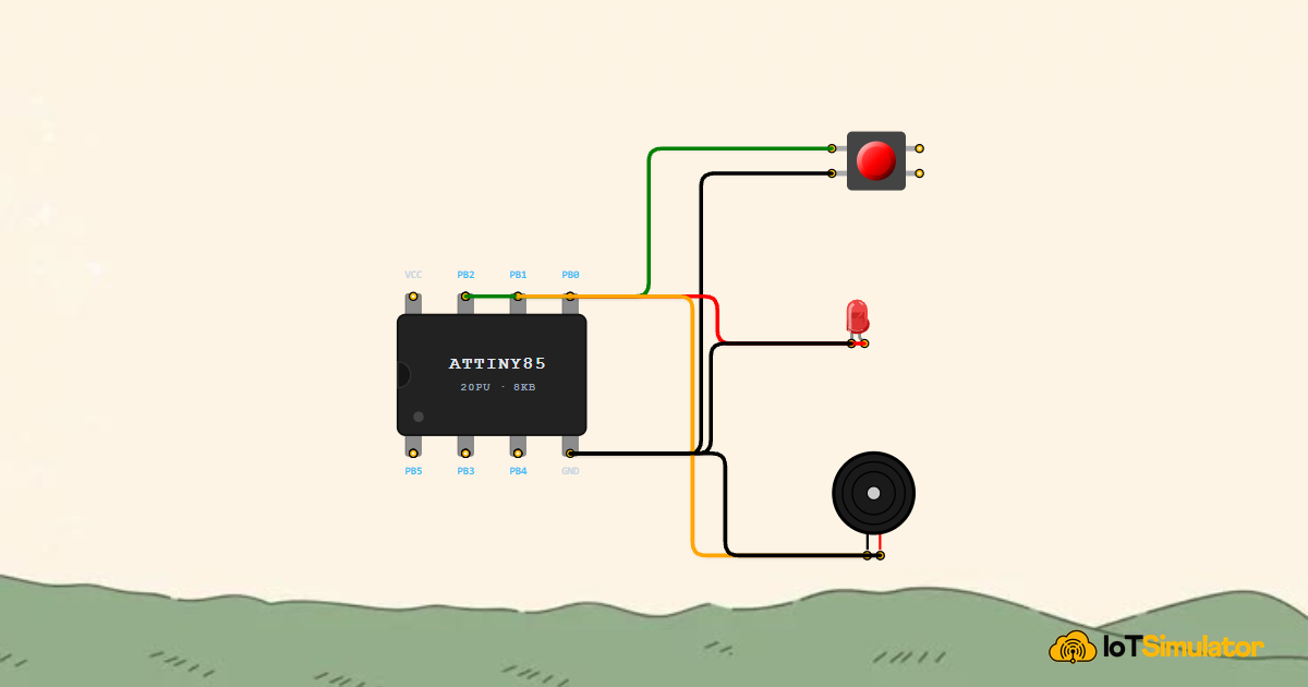
The ATtiny85 is an 8-pin chip, so wiring is straightforward. The button goes to pin PB2, which is configured with an internal pull-up resistor, so you do not need any external resistor. The LED connects to PB0, and the buzzer connects to PB1. All three components share the same ground rail (physical pin 4).
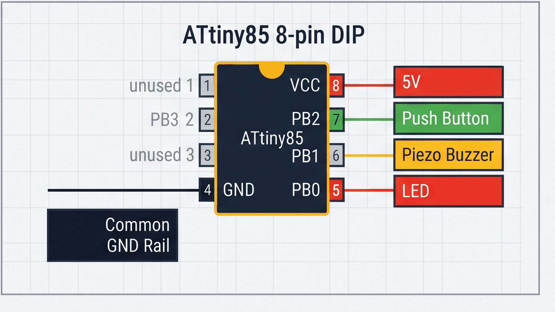
The diagram shows which physical pins connect to which component. Pins 1, 2, and 3 on the left side are unused in this project. The right side carries all the active signals: power on pin 8, the button input on pin 7, the buzzer on pin 6, and the LED on pin 5. All three components return their ground connection to pin 4.
Next, connect the red LED indicator circuit to physical pin 5 (PB0) through a 220Ω current-limiting resistor to emit visible optical Morse pulses:
Finally, wire the piezo buzzer to physical pin 6 (PB1) so the beacon generates synchronized acoustic sound bursts alongside each optical flash:
Once wired, the button uses the ATtiny85's built-in pull-up resistor — INPUT_PULLUP in code — so no external components are needed. Pressing the button connects PB2 directly to ground, which the chip reads as a LOW signal and uses as the trigger to start broadcasting SOS.
Complete Code
The sketch below is the full program. Everything is built around one helper function called beep(), which turns the LED and buzzer on, waits for the right duration, then turns them off and leaves a short gap before the next signal.
// ATtiny85 SOS Beacon
// Press the button → LED flashes + buzzer beeps in SOS pattern

const int BTN_PIN  = 2; // PB2, Physical Pin 7
const int LED_PIN  = 0; // PB0, Physical Pin 5
const int BUZZ_PIN = 1; // PB1, Physical Pin 6

const int DOT = 150; // one dot = 150 ms

void beep(int duration) {
  digitalWrite(LED_PIN, HIGH);
  tone(BUZZ_PIN, 1000);
  delay(duration);
  digitalWrite(LED_PIN, LOW);
  noTone(BUZZ_PIN);
  delay(DOT); // short gap between signals
}

void setup() {
  pinMode(BTN_PIN, INPUT_PULLUP);
  pinMode(LED_PIN, OUTPUT);
  pinMode(BUZZ_PIN, OUTPUT);
}

void loop() {
  if (digitalRead(BTN_PIN) == LOW) {
    // S: three short dots
    for (int i = 0; i < 3; i++) beep(DOT);
    delay(DOT * 2); // letter gap

    // O: three long dashes
    for (int i = 0; i < 3; i++) beep(DOT * 3);
    delay(DOT * 2); // letter gap

    // S: three short dots
    for (int i = 0; i < 3; i++) beep(DOT);
    delay(DOT * 6); // word gap before repeating
  }
}
How the Code Works, Part by Part
The sketch has four sections: the pin declarations, the beep() helper, the setup() function, and the loop(). Each one has a specific job, and together they produce a complete, repeating SOS signal every time the button is held down.
▸ Pin Declarations and the DOT Constant
The three const int lines name the pins so the rest of the code reads like plain English instead of raw numbers. The DOT constant is the heart of the timing system — change it to 100 and the beacon speeds up, change it to 200 and it slows down. Every duration in the program is derived from this one value.
const int BTN_PIN  = 2; // PB2, Physical Pin 7
const int LED_PIN  = 0; // PB0, Physical Pin 5
const int BUZZ_PIN = 1; // PB1, Physical Pin 6

const int DOT = 150; // one dot = 150 ms
Using named constants also makes it easy to change pins if you wire the project differently. Instead of hunting through the whole sketch for the number 0, you just update LED_PIN in one place.
▸ The beep() Helper Function
The beep(duration) function is called with either DOT (150 ms) for a short signal or DOT * 3 (450 ms) for a long signal. It turns the LED and buzzer on at exactly the same moment, waits, then turns them both off and leaves a 1T gap of silence before the next signal can begin. That final delay(DOT) is the intra-signal gap that separates consecutive dots or dashes inside one letter.
void beep(int duration) {
  digitalWrite(LED_PIN, HIGH);
  tone(BUZZ_PIN, 1000);
  delay(duration);
  digitalWrite(LED_PIN, LOW);
  noTone(BUZZ_PIN);
  delay(DOT); // short gap between signals
}
Packaging the signal logic in its own function keeps the main loop() clean and readable. If you ever want to change the buzzer frequency, you only need to update the number inside tone() once, right here.
▸ Sending the SOS Pattern
The loop() polls the button every cycle. If the button is pressed (LOW), the program runs through three groups of calls: S is three short beep(DOT) calls, O is three long beep(DOT * 3) calls, and S again is three short calls. Between each letter, a delay(DOT * 2) adds the extra silence needed to reach a full 3T gap (the beep() function already adds 1T at the end, so only 2T more is needed). After the final S, a longer delay(DOT * 6) creates the 7T word pause before the pattern can restart.
void loop() {
  if (digitalRead(BTN_PIN) == LOW) {
    // S: three short dots
    for (int i = 0; i < 3; i++) beep(DOT);
    delay(DOT * 2); // letter gap

    // O: three long dashes
    for (int i = 0; i < 3; i++) beep(DOT * 3);
    delay(DOT * 2); // letter gap

    // S: three short dots
    for (int i = 0; i < 3; i++) beep(DOT);
    delay(DOT * 6); // word gap before repeating
  }
}
Notice that as long as the button is held down, the SOS sequence will play all the way through before the if check runs again. Releasing the button mid-sequence will not cut it short — the current cycle finishes first, then the chip returns to idle waiting on the next pass through loop().
Fixing Common Problems
If the simulation does not behave as expected, here are the most common causes and how to fix them.
| What you see | Likely cause | What to try |
|---|---|---|
| Beacon fires on its own without pressing the button | Button pin is floating or connected wrongly | Check that INPUT_PULLUP is set in setup() and that the button's second terminal goes to GND |
| LED flashes but buzzer stays silent | Buzzer wired to the wrong pin | Confirm the buzzer positive lead is on PB1 (physical pin 6), not PB0 |
| Pattern timing feels 8× too slow | ATtiny85 running at 1 MHz instead of 8 MHz | Re-flash the bootloader with 8 MHz Internal Clock selected in board settings |
| Pressing the button causes multiple rapid triggers | Button bounce — the contact rattles for a few milliseconds | Add a small delay(50) after detecting the button press before starting the SOS loop |
The most common issue for first-time ATtiny85 users is the clock speed. The chip ships defaulting to 1 MHz, which makes every timing value eight times too slow. If your dots sound like dashes, that is almost certainly the reason.
Try It in the Simulator
Click the Start Simulation (▶) button in the toolbar to bring the circuit to life. Then click the SOS Button on the canvas and watch the LED and buzzer respond together. You will see three short flashes, three long flashes, and three short flashes — the unmistakable SOS rhythm. The simulation pauses after each complete cycle before waiting for the next button press.
More in ATtiny85
More in Audio
More in Display
More in Beginner
Build a 4-Key Piano Synthesizer with a Raspberry Pi Pico W
Control a Servo Positioner with a Raspberry Pi Pico
Build a Light Meter and Alarm with a Raspberry Pi Pico
Build a Motion Security Chime with an Arduino Nano