Control a Servo with an ATtiny85 and Potentiometer

Live project track
When you turn a volume dial on a stereo or steer a remote-control car, you expect the output to follow your hand smoothly and immediately. Servo motors make this kind of control possible. Unlike standard DC motors that spin continuously without stopping, a servo motor rotates to a specific commanded angle and holds its position firmly.
In this project, you will build a knob-controlled servo system using an ATtiny85 microcontroller, a 10k rotary potentiometer, and an SG90 micro servo. The main idea is straightforward: turning the potentiometer changes the analog voltage entering the microcontroller, and the ATtiny85 converts that voltage into microsecond timing pulses that instruct the servo arm where to point in real time.
How a Servo Understands Pulse Timing
A servo motor does not read raw analog voltage like a sensor does. Inside the servo casing sits a small control circuit that listens for repeated electrical pulses delivered 50 times every second (once every 20 milliseconds). The width of each high pulse tells the internal motor exactly which angle to turn to.
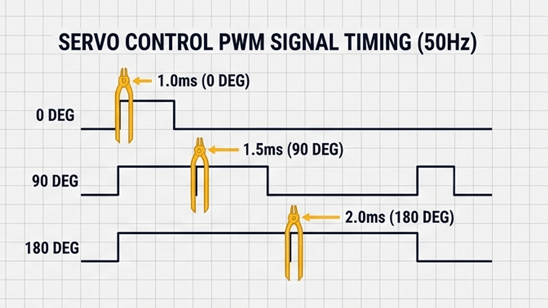
The waveform diagram above illustrates the three key reference positions. An active pulse lasting 1.0 millisecond (1000 microseconds) instructs the servo horn to rotate to 0 degrees (full left). A 1.5 millisecond pulse (1500 microseconds) commands it to hold the center position at 90 degrees. A 2.0 millisecond pulse (2000 microseconds) commands it to full right at 180 degrees. Any pulse duration in between positions the motor arm proportionally across its full movement range.
| High pulse duration | Duration in microseconds | Target horn angle | Position description |
|---|---|---|---|
| 1.0 ms | 1000 µs | 0° | Full left |
| 1.5 ms | 1500 µs | 90° | Neutral center |
| 2.0 ms | 2000 µs | 180° | Full right |
Because the total time between pulses must stay consistent at 20 milliseconds (20,000 microseconds), the quiet rest time between pulses simply equals 20,000 minus your active pulse duration. This steady rhythm gives the servo motor continuous torque to hold its commanded position.
Turning Knob Values into Servo Pulses
A rotary potentiometer acts as an adjustable voltage divider. As you turn the knob from left to right, the voltage on its middle wiper pin slides smoothly between 0 volts and 5 volts. The ATtiny85 reads this voltage through its internal analog-to-digital converter (ADC), converting the measurement into a number from 0 to 1023.
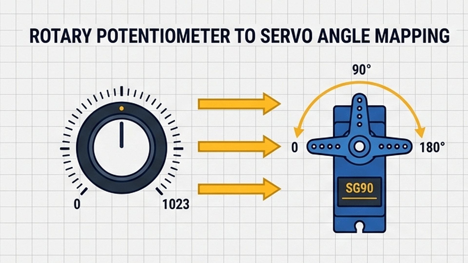
The flow diagram above traces the signal through the entire system. The microcontroller reads the 0–1023 number, uses the built-in map() function to scale it into the 1000–2000 microsecond range, and sends the resulting pulse straight to the servo signal pin. As your fingers turn the knob, the servo arm mirrors your movement without lag.
| Knob position | Wiper voltage | analogRead(A1) value | Generated pulse width | Servo angle |
|---|---|---|---|---|
| Full counter-clockwise | 0.0 V | 0 | 1000 µs | 0° (Left) |
| Halfway turned | 2.5 V | ~512 | 1500 µs | 90° (Center) |
| Full clockwise | 5.0 V | 1023 | 2000 µs | 180° (Right) |
By creating pulses directly using delayMicroseconds(), this approach operates without heavy external servo libraries. This keeps the program tiny and ensures it fits easily into the ATtiny85's compact memory footprint.
Connecting the Circuit
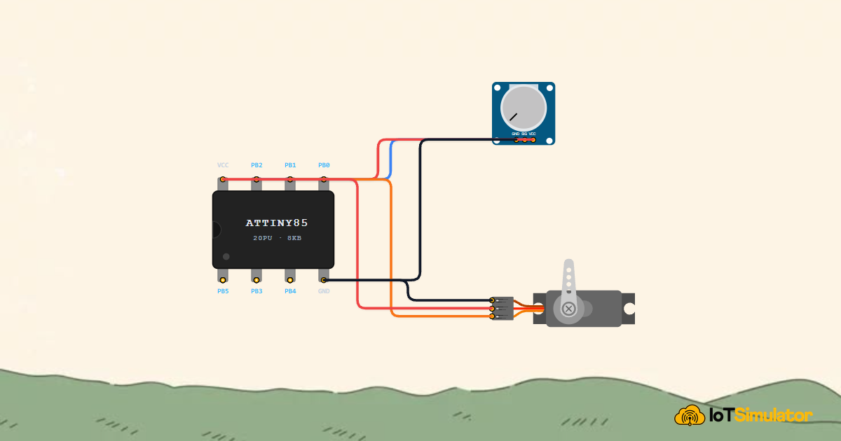
The circuit links two simple physical actions: rotating the potentiometer knob and watching the servo motor arm mirror that exact angle. Because the ATtiny85 has only eight pins, every wire has a single direct job.
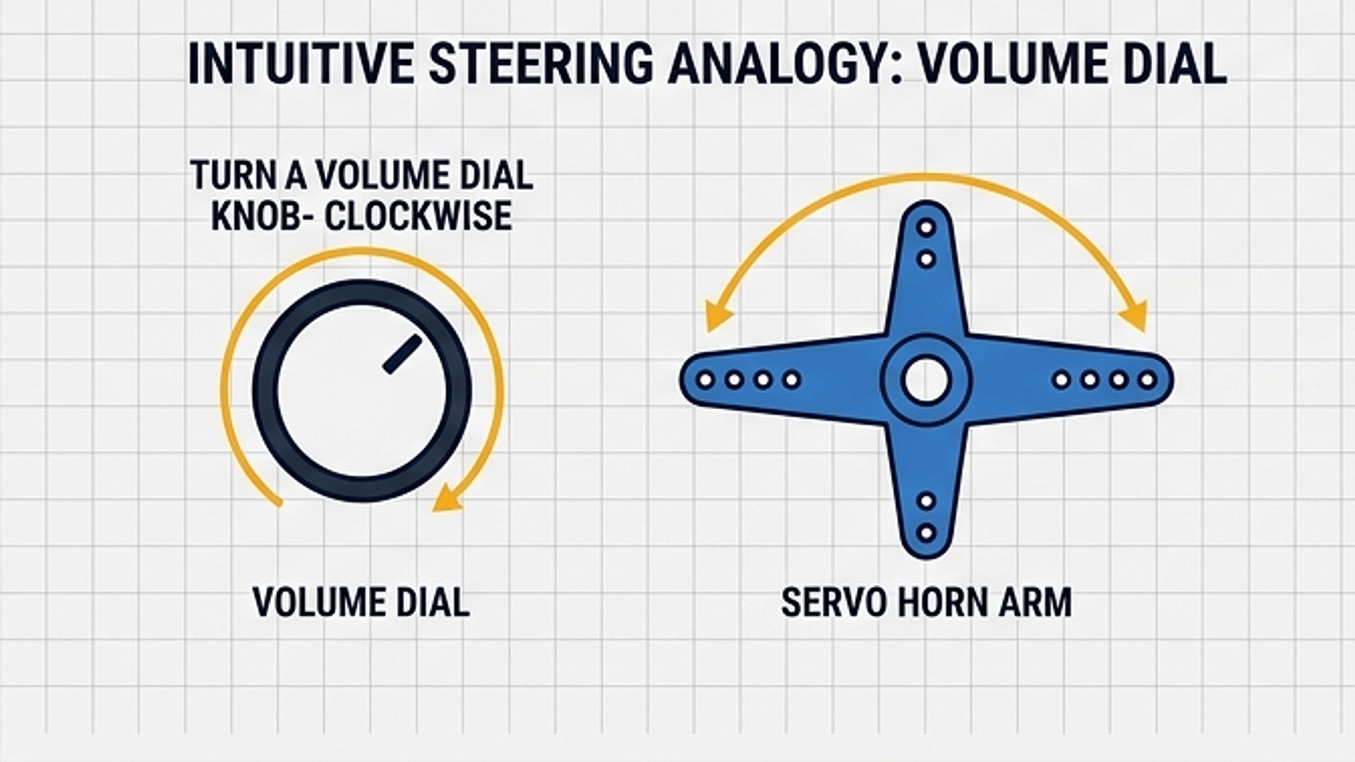
As shown in the diagram, turning the knob smoothly turns the motor horn like a car steering wheel or a miniature barrier gate. Connect the potentiometer signal and servo control wires to the ATtiny85 pins as detailed below:
Next, connect the SG90 micro servo control wire to physical pin 5 (PB0) along with its 5V power and ground supply leads:
When working with physical hardware on a breadboard, servo motors can briefly draw up to 500 milliamps when starting or reversing direction quickly. Placing a 100µF or 470µF capacitor between 5V and GND close to the servo will smooth out power surges and prevent the microcontroller from resetting.
Complete Code
Here is the complete Arduino sketch. It reads the potentiometer, maps the measurement to a microsecond pulse duration, and transmits the standard 50Hz servo frame continuously.
// ============================================================================
// ATtiny85 Knob-Controlled Servo Motor
// Reads Potentiometer on Physical Pin 7 (PB2 / ADC1 / Analog Pin A1)
// Drives SG90 Servo on Physical Pin 6 (PB1 / Digital Pin 1)
// ============================================================================

const int POT_PIN   = A1; // PB2 (Physical Pin 7 on DIP-8) - Analog Input
const int SERVO_PIN = 1;  // PB1 (Physical Pin 6 on DIP-8) - Servo Control Output

void setup() {
  // Configure the servo pin as an output
  pinMode(SERVO_PIN, OUTPUT);
}

void loop() {
  // 1. Read the knob position (0 = full left, 1023 = full right)
  int potVal = analogRead(POT_PIN);

  // 2. Convert knob reading to microsecond pulse duration (1000µs to 2000µs)
  int pulseWidth = map(potVal, 0, 1023, 1000, 2000);

  // 3. Transmit standard 50Hz servo frame (20ms total duration)
  digitalWrite(SERVO_PIN, HIGH);
  delayMicroseconds(pulseWidth);        // Active high pulse (1ms - 2ms)
  digitalWrite(SERVO_PIN, LOW);
  delayMicroseconds(20000 - pulseWidth); // Low rest period to complete 20ms
}
How the Code Works, Part by Part
The entire program runs inside a continuous loop with no complex background libraries. Each cycle completes three simple tasks: sample the knob, calculate the pulse duration, and transmit the pulse.
▸ Pin Declarations and Setup
The program begins by defining descriptive names for both pins. On the ATtiny85, PB2 is associated with analog channel 1, so we reference it with the alias A1. Physical pin 6 is Port B Pin 1, configured as digital output 1.
const int POT_PIN   = A1; // PB2 (Physical Pin 7 on DIP-8)
const int SERVO_PIN = 1;  // PB1 (Physical Pin 6 on DIP-8)

void setup() {
  pinMode(SERVO_PIN, OUTPUT);
}
We only configure SERVO_PIN with pinMode() because analog input pins are initialized automatically when analogRead() is called.
▸ Reading the Dial and Mapping to Microseconds
Inside loop(), the program reads the instantaneous wiper voltage from POT_PIN. It then passes that value into map() to rescale the integer range from 0–1023 into 1000–2000 microseconds.
int potVal = analogRead(POT_PIN);
int pulseWidth = map(potVal, 0, 1023, 1000, 2000);
The map() function uses fast integer math to translate the numbers proportionally. If potVal is 0, pulseWidth becomes 1000. If potVal is 1023, pulseWidth becomes 2000.
▸ Transmitting the Precision 50Hz Frame
To deliver the pulse to the servo motor, the code drives SERVO_PIN HIGH and holds it for pulseWidth microseconds. It then pulls the pin LOW and holds it for 20000 - pulseWidth microseconds.
digitalWrite(SERVO_PIN, HIGH);
delayMicroseconds(pulseWidth);
digitalWrite(SERVO_PIN, LOW);
delayMicroseconds(20000 - pulseWidth);
Notice how the two delays always add up to exactly 20,000 microseconds (20 ms). Whether the high pulse is short (1000 µs) or long (2000 µs), the total frame repetition rate remains locked at 50Hz, keeping the motor steady and responsive.
Fixing Common Problems
If the servo does not track the knob or behaves unexpectedly, use the troubleshooting table below to identify the issue.
| What you see | Likely cause | What to try |
|---|---|---|
| Servo does not turn at all | Pin assignment mismatch or reversed power wiring | Verify servo signal connects to PB1 (Pin 6) and power leads are 5V (Red) and GND (Brown) |
| Servo jerks or resets constantly when moving knob | Power supply voltage dips from motor current surge | Power the servo from an external 5V supply or add a 100µF capacitor across 5V and GND |
| Servo moves through only half its full travel | Servo model expects wider 500µs–2500µs pulse range | Update code mapping to map(potVal, 0, 1023, 500, 2500) |
| Servo buzzes or chatters when knob is still | Small electrical noise on potentiometer wiper | Twist your jumper wires together or introduce a 5-unit deadband filter in code |
Some hobby servos support an extended pulse range beyond the standard 1000µs–2000µs window. If your servo only covers about 90 degrees of travel, broadening the target range in the map() function will allow it to access its full 180-degree physical range.
Try It in the Simulator
Click the Start Simulation (▶) button in the top toolbar to begin. Click and drag the rotary dial on the Position Knob component from minimum to maximum. Watch the SG90 Servo arm track the knob's position in real time across the full 180-degree sweep!
More in ATtiny85
More in Servo Motor
More in Motors
More in Intermediate
Build a Smart Climate Monitor with a Raspberry Pi Pico W
Build a Multi-Room Safety Monitor with an Arduino Mega
Build a Keypad Door Lock with an Arduino Mega
Control a Pan and Tilt Servo with an Arduino Mega and Joystick