Blink an LED with an ATtiny85

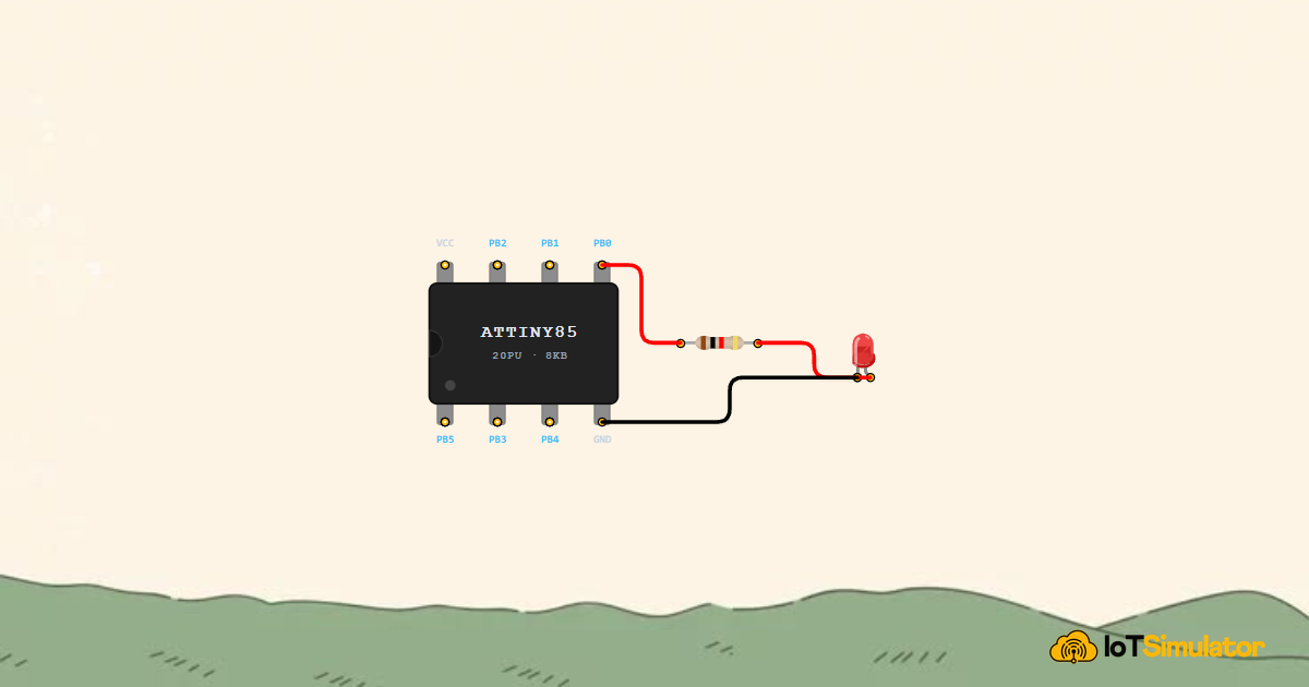
Live project track
Every microcontroller project starts here. Blink an LED, confirm the chip is alive, confirm the wiring is right, confirm the code uploaded — then move on to bigger things. It sounds simple, but making a light blink on command is the moment a chip stops being a piece of plastic and starts doing something useful. The ATtiny85 is a tiny 8-pin chip, and this is the first thing you should build with it.
In this project, you will connect a red LED and a 220Ω resistor to an ATtiny85 microcontroller and program it to blink once per second. The main ideas are two: a resistor is always needed to protect the LED from too much current, and the chip's PB0 pin (physical pin 5) is called pin 0 in your code.
Why the LED Needs a Resistor
An LED is not a light bulb — it does not naturally limit how much current flows through it. If you connect an LED directly to 5V without a resistor, current rushes through unchecked and the LED burns out in seconds. The 220Ω resistor sits in the path of that current and slows it down to a safe level, around 14 milliamps, which is bright enough to see clearly but low enough to protect both the LED and the ATtiny85 pin that is driving it.
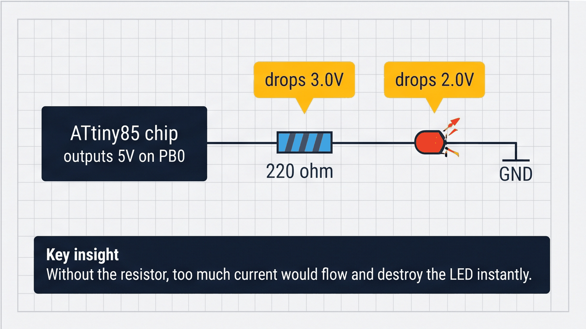
The diagram shows how voltage is shared across the circuit. The total supply is 5V. The resistor uses up 3V of that, leaving 2V across the LED — exactly what a standard red LED needs. Think of it like a pipe with a narrow section in the middle: the narrow part (the resistor) controls how fast water (current) flows through the whole pipe.
| Component | Voltage used | What it does |
|---|---|---|
| 220Ω Resistor | 3.0V | Slows current to a safe ~14 mA |
| Red LED | 2.0V | Converts current into light |
| Total | 5.0V | Full supply voltage accounted for |
If you ever swap the LED for a different color, the voltage it needs changes slightly — blue and white LEDs use about 3.0–3.3V instead of 2V. The same 220Ω resistor still works fine for a beginner project, though the LED will be slightly dimmer.
Understanding the ATtiny85 Pins
The ATtiny85 has 8 physical pins, but only 6 of them are usable as inputs or outputs (two are power and ground). The chip is small enough to hold between two fingers, but it has everything needed to run a full program. The most important thing to understand before wiring is that the physical pin numbers on the chip and the pin numbers you type in your code are different.
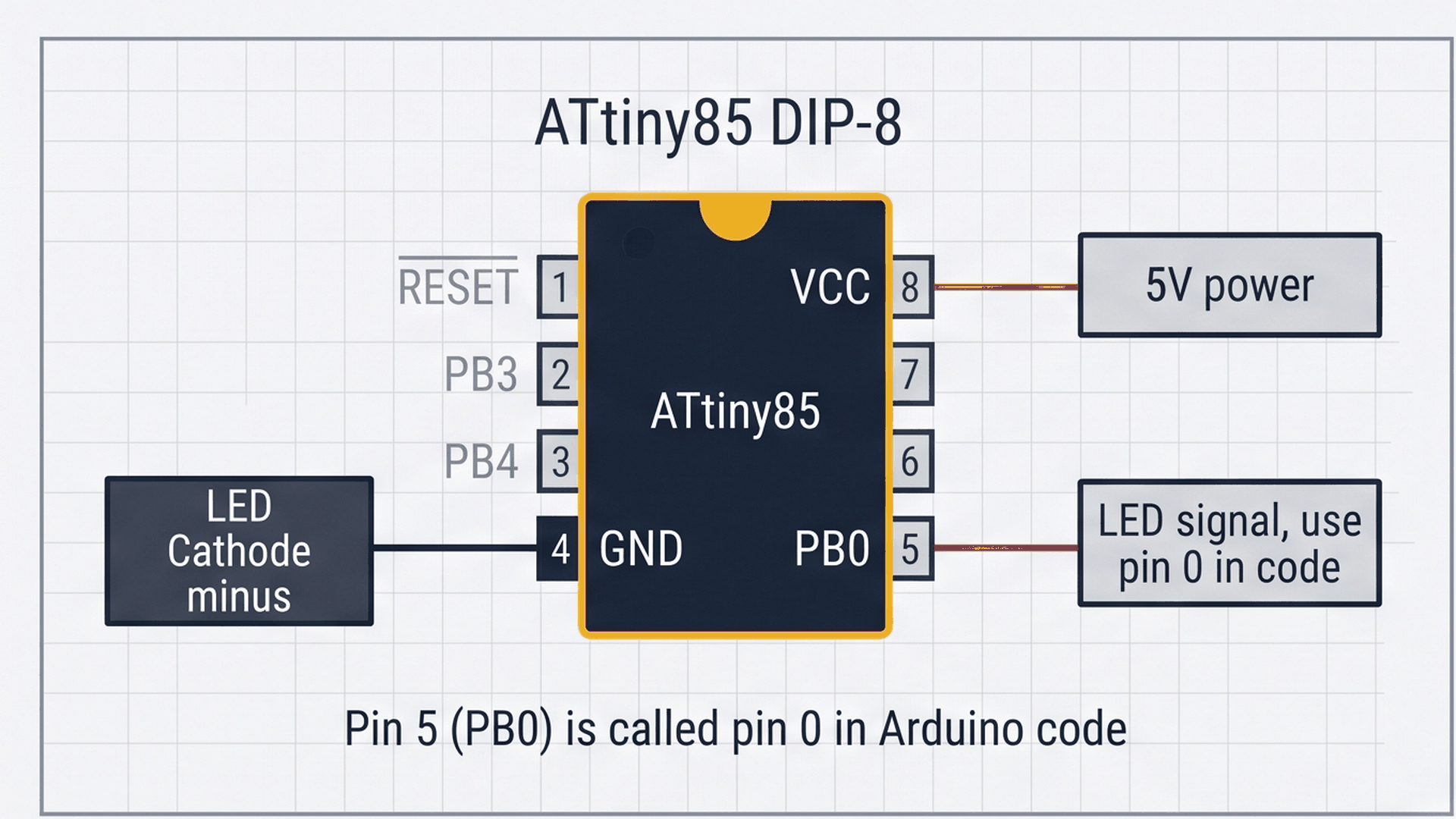
The diagram above shows the chip with its notch at the top. Physical pin 5 (bottom-right) is called PB0 in hardware terms, but in your Arduino code you refer to it simply as pin 0. Physical pin 4 (bottom-left) is GND — this is the negative return for everything in the circuit. You do not type a number for GND in your code; the chip handles that connection automatically.
| Physical pin | Name | Code pin | Used in this project |
|---|---|---|---|
| Pin 4 | GND | — | ✅ Ground (LED return path) |
| Pin 5 | PB0 | 0 | ✅ LED output signal |
| Pin 8 | VCC | — | ✅ 5V power supply |
| Pins 1–3, 6–7 | PB1–PB5 | 1–5 | Unused in this project |
When wiring the circuit, hold the chip with the notch at the top. Pins 1–4 run down the left side, and pins 5–8 run up the right side. Your LED connects from pin 5 (through the resistor) down to pin 4 — physically right next to each other on the chip.
Connecting the Circuit
The wiring is three connections: the ATtiny85 output to the resistor, the resistor to the LED anode, and the LED cathode back to GND. The resistor is not polarized — either end can face the chip. The LED is polarized — the longer leg (anode) faces the resistor, and the shorter leg (cathode) faces GND.
A common beginner mistake is plugging the LED in backwards. If the LED does not light up and everything else looks correct, try flipping the LED around. The flat edge on the LED body and the shorter leg both mark the cathode (negative) side.
Complete Code
The sketch below is the full program. It is eight lines of actual logic — short enough to read in one glance and understand completely.
// ATtiny85 LED Blink
// Turns an LED on for 500ms then off for 500ms, repeating forever

const int LED_PIN = 0;        // PB0, Physical Pin 5
const int BLINK_INTERVAL = 500; // milliseconds on / off

void setup() {
  pinMode(LED_PIN, OUTPUT);
}

void loop() {
  digitalWrite(LED_PIN, HIGH); // LED on
  delay(BLINK_INTERVAL);
  digitalWrite(LED_PIN, LOW);  // LED off
  delay(BLINK_INTERVAL);
}
How the Code Works, Part by Part
Even though the sketch is short, each line has a specific purpose. Understanding what each line does gives you the building blocks for every other ATtiny85 project.
▸ The Two Constants
LED_PIN = 0 gives the number a readable name so you never have to remember that pin 0 means physical pin 5. BLINK_INTERVAL = 500 sets the on/off time in milliseconds. Changing this one number changes the blink speed everywhere in the program at once — set it to 100 for a fast flicker, or 2000 for a slow two-second pulse.
const int LED_PIN = 0;          // PB0, Physical Pin 5
const int BLINK_INTERVAL = 500; // milliseconds on / off
Using named constants instead of raw numbers is a good habit even in small programs. If you add a second LED on a different pin later, you add a second constant with a clear name rather than hunting through the code for bare numbers.
▸ setup() — Runs Once at Startup
pinMode(LED_PIN, OUTPUT) tells the ATtiny85 to configure pin 0 as an output, meaning the chip will drive it either HIGH (5V) or LOW (0V). Without this line, the pin defaults to an input and digitalWrite() would have no effect.
void setup() {
  pinMode(LED_PIN, OUTPUT);
}
setup() runs exactly once when the chip powers on or resets. Everything you put here happens before the main loop begins. For this project, one line is all it needs.
▸ loop() — Runs Forever
After setup() finishes, the chip jumps into loop() and stays there forever, repeating it from top to bottom continuously. The four lines inside do: turn LED on → wait 500ms → turn LED off → wait 500ms → repeat. The delay() function pauses the chip for the given number of milliseconds while holding the pin at whatever level it was last set to.
void loop() {
  digitalWrite(LED_PIN, HIGH); // LED on
  delay(BLINK_INTERVAL);
  digitalWrite(LED_PIN, LOW);  // LED off
  delay(BLINK_INTERVAL);
}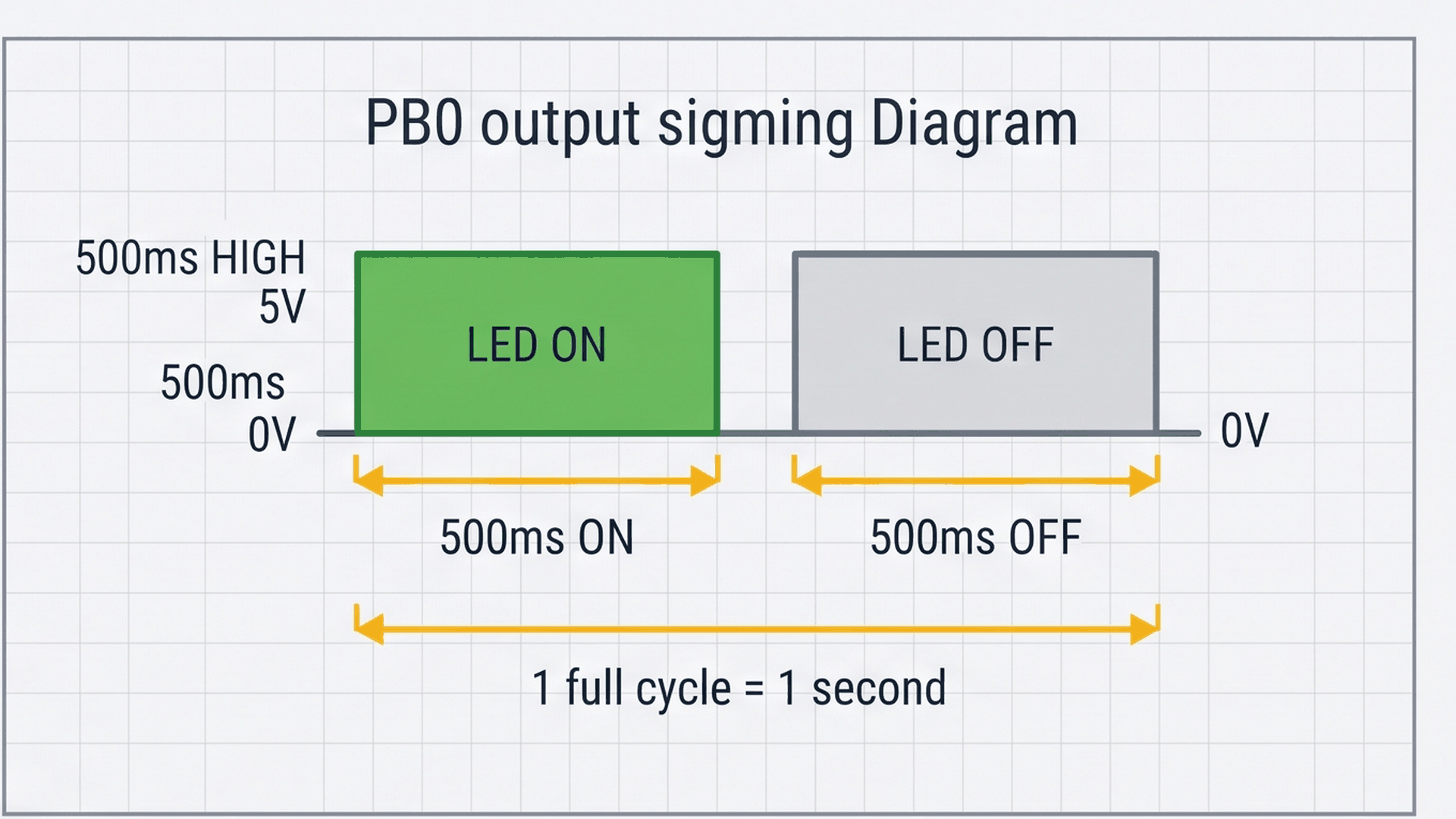
The diagram shows what the output signal looks like over time. The pin switches between 5V and 0V in a perfectly regular rhythm, once per second. Each HIGH phase is 500ms (the LED is on), each LOW phase is 500ms (the LED is off), and the whole cycle takes exactly 1 second.
Fixing Common Problems
If the LED does not blink as expected, the table below covers the most likely causes.
| What you see | Likely cause | What to try |
|---|---|---|
| LED stays completely off | LED is wired backwards (cathode facing resistor) | Flip the LED around — longer leg faces the resistor |
| LED stays always on | Wrong pin number in code (e.g. wrote 5 instead of 0) | Use 0 for PB0, not the physical pin number 5 |
| Blink is 8× too slow (4 sec instead of 0.5 sec) | ATtiny85 running at 1 MHz instead of 8 MHz | In Arduino IDE → Tools → Clock: select Internal 8 MHz and burn bootloader |
| Very dim glow, barely visible | Wrong resistor value — might be 220 kΩ instead of 220Ω | Check resistor color bands: Red–Red–Brown–Gold = 220Ω |
The clock speed issue is extremely common for ATtiny85 beginners. The chip ships from the factory running at 1 MHz with a clock divider turned on, which makes every delay(500) feel like delay(4000). Burning the bootloader with 8 MHz selected fixes it permanently.
Try It in the Simulator
Click Start Simulation (▶) in the toolbar. The red LED on the canvas will immediately begin blinking — on for half a second, off for half a second. Try editing BLINK_INTERVAL in the code panel: change it to 100 and restart to see a rapid flicker, or 2000 for a slow two-second pulse. The simulator responds instantly to code changes.
More in ATtiny85
More in LED

More in Beginner
Build a 4-Key Piano Synthesizer with a Raspberry Pi Pico W
Control a Servo Positioner with a Raspberry Pi Pico
Build a Light Meter and Alarm with a Raspberry Pi Pico
Build a Motion Security Chime with an Arduino Nano