Control an RGB LED with an ATtiny85 and Push Button

Live project track
Every electronic gadget with a single multi-color status light — from wireless earbuds and smart speakers to computer power buttons — uses one LED to convey multiple messages. Green means battery charged, red means low battery, blue means pairing mode, and a flashing pattern means syncing. Behind each of those lights is a controller switching color channels in response to events or button presses.
In this project, you will build a multi-mode color controller using an ATtiny85 microcontroller, a push button, and a common-cathode RGB LED. The main idea is that an RGB LED contains three separate LED chips inside one package — red, green, and blue. By turning those three color channels on and off in different combinations, you can produce almost any color you want and cycle through them each time you press the button.
How an RGB LED Mixes Colors
An RGB LED looks like a normal light bulb on the outside, but inside its plastic dome sit three tiny, independent LEDs: one red, one green, and one blue. When you turn on just one channel, you see that pure primary color. When you turn on two channels together, the colors blend in your eyes to create a brand new secondary color — red plus green makes yellow, green plus blue makes cyan, and red plus blue makes magenta.
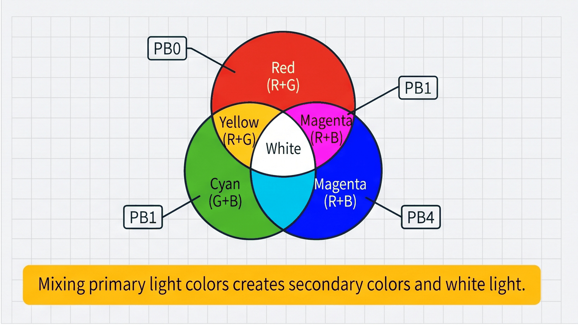
The diagram above illustrates additive color mixing. In the real world, mixing light works differently than mixing paint. Adding all three light channels together produces crisp white light, while turning all three off leaves the LED dark. Because each color channel is wired to its own microcontroller pin, your code can toggle any combination with simple HIGH and LOW commands.
| Desired color | Red channel (PB0) | Green channel (PB1) | Blue channel (PB4) |
|---|---|---|---|
| Red | HIGH | LOW | LOW |
| Green | LOW | HIGH | LOW |
| Blue | LOW | LOW | HIGH |
| Yellow | HIGH | HIGH | LOW |
| Cyan | LOW | HIGH | HIGH |
| Magenta | HIGH | LOW | HIGH |
| White | HIGH | HIGH | HIGH |
To keep your sketch clean and maintainable, a small helper function can set all three channels in a single line of code instead of writing three separate digitalWrite() calls every time you switch colors.
Switching Modes with a Single Button
Instead of requiring multiple buttons to select each color, this circuit uses one push button that steps forward through a list of four lighting modes. Each time you press and release the button, the active mode number increases by one. When it reaches the end of the list, it wraps smoothly back to the beginning so you can cycle through the modes indefinitely.
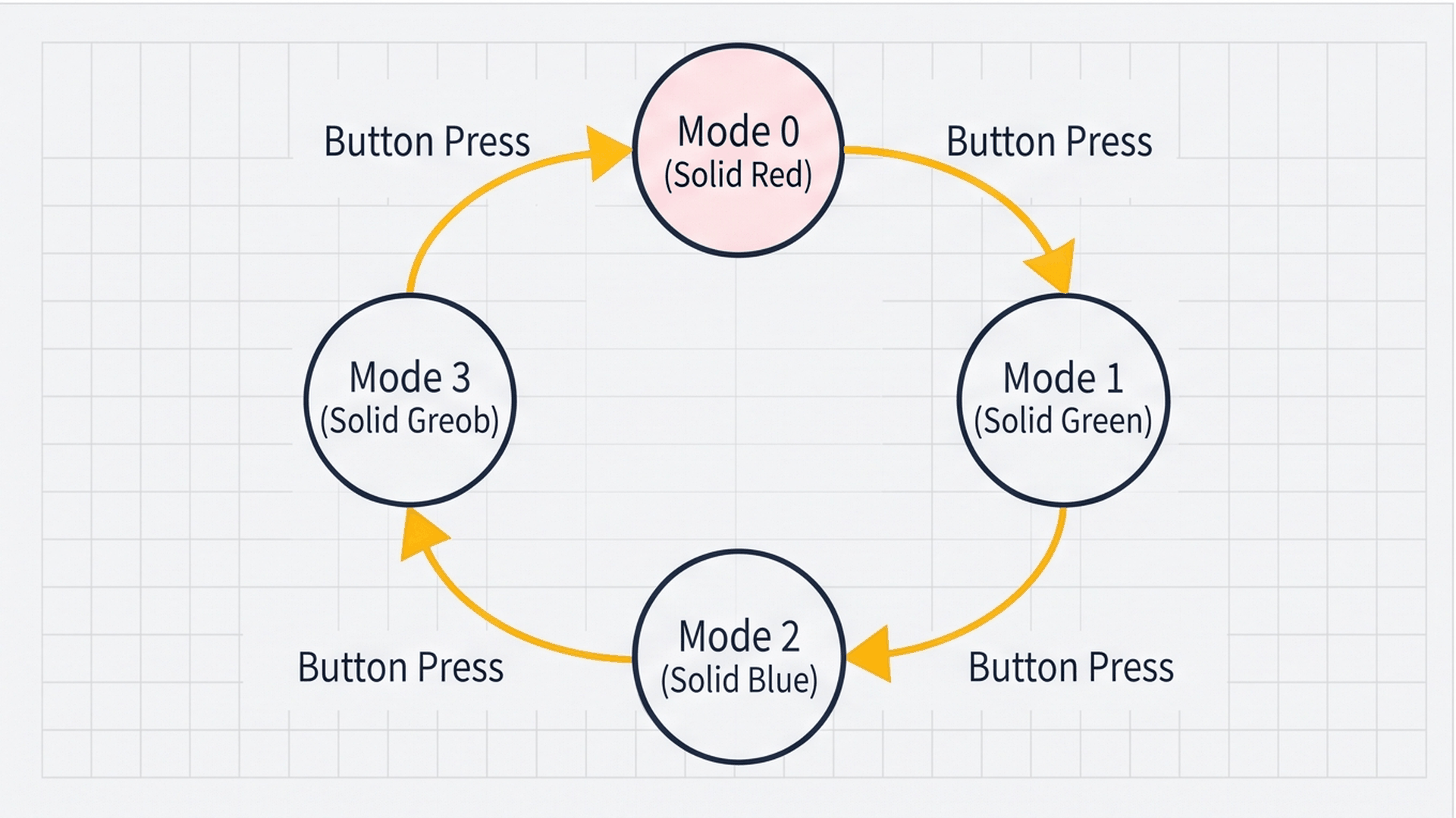
The diagram shows the circular cycle of states. The system begins in Mode 0 (Solid Red). Pressing the button advances the system to Mode 1 (Solid Green), then Mode 2 (Solid Blue), and Mode 3 (Rainbow Strobe). A fourth click returns the system cleanly back to Mode 0. The modulo operator in code ((currentMode + 1) % 4) handles this continuous wrap-around automatically.
| Mode number | Display name | What the LED does |
|---|---|---|
| Mode 0 | Solid Red | Red channel stays continuously on |
| Mode 1 | Solid Green | Green channel stays continuously on |
| Mode 2 | Solid Blue | Blue channel stays continuously on |
| Mode 3 | Rainbow Strobe | Steps through 6 colors every 120 ms without freezing |
Notice that in Mode 3, the colors animate continuously without freezing the microcontroller. This is achieved using a non-blocking timer with millis() rather than delay(), ensuring the button remains responsive even while the light flashes rapidly.
Connecting the Circuit
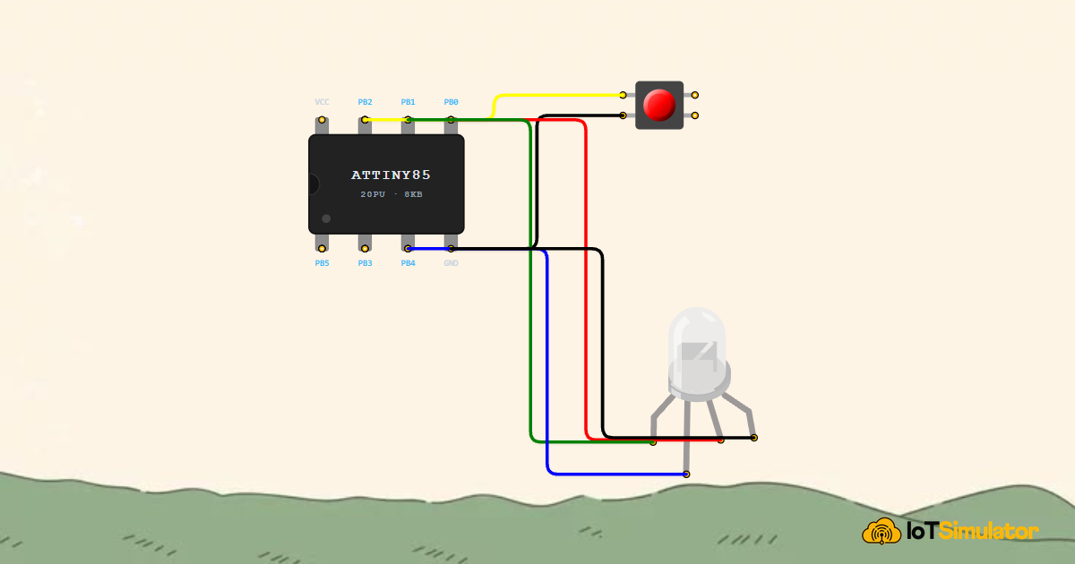
The ATtiny85 has only 8 physical pins, making pin planning essential. The push button connects to PB2 (physical pin 7) with an internal pull-up resistor, eliminating the need for an external resistor. The three color anodes of the RGB LED connect to PB0 (pin 5), PB1 (pin 6), and PB4 (pin 3). Crucially, each color channel requires its own 220Ω resistor.
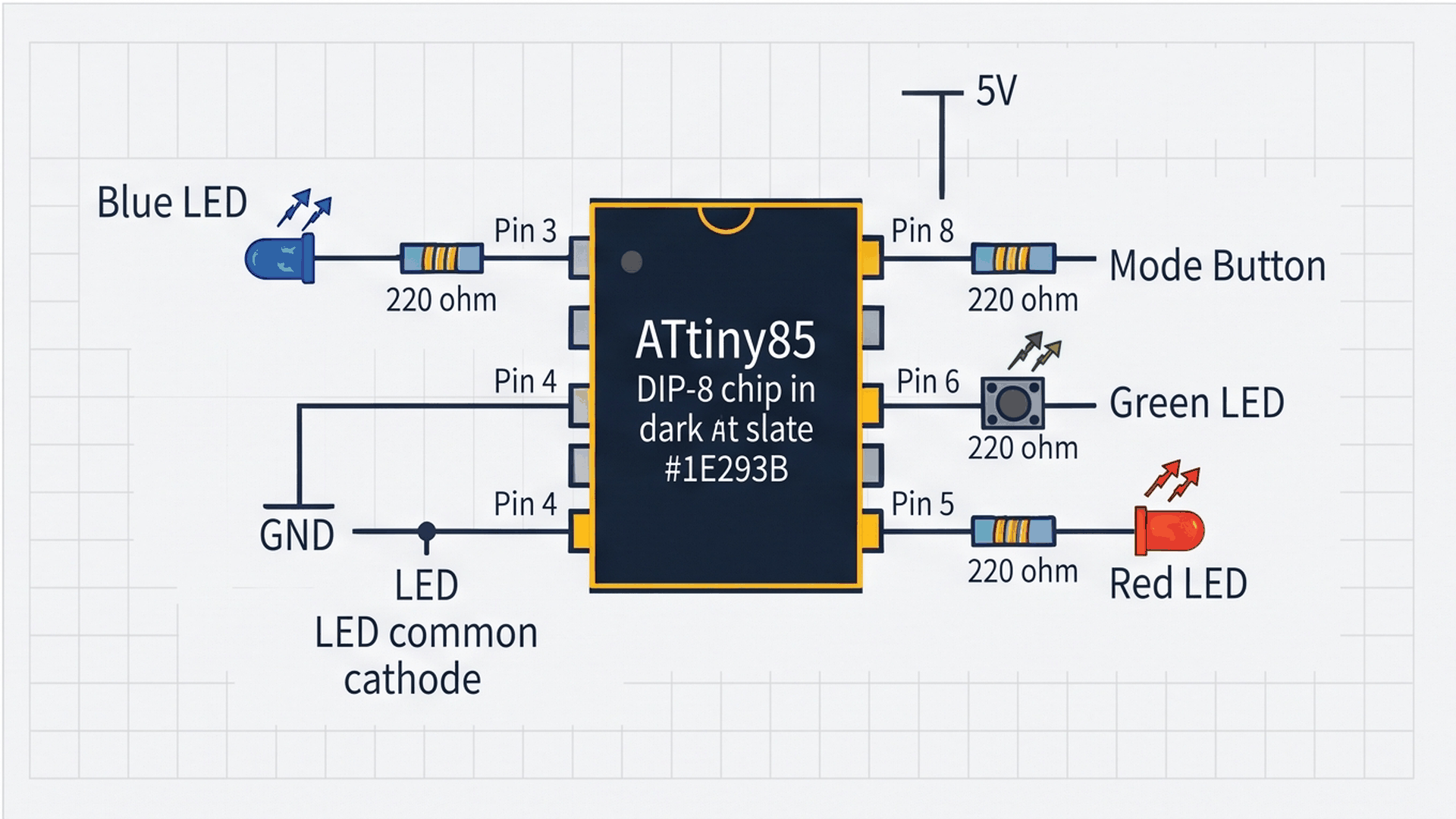
The schematic above shows how every pin is routed. Physical pin 4 serves as the common ground connection for both the button and the RGB LED cathode. Pins 1 and 2 on the left side of the chip remain unused. Notice that on a 4-pin RGB LED, the longest lead is always the common cathode pin.
Next, connect each color channel anode of the RGB LED through dedicated current-limiting resistors to the ATtiny85 output pins:
Finally, wire the common terminal of the RGB LED to complete the circuit return path back to the power rail:
Why does each color channel need its own resistor instead of sharing a single resistor on the ground pin? Red LEDs require about 2.0 volts to turn on, while green and blue LEDs need about 3.2 volts. If all three shared one ground resistor, the red channel would turn on first and starve the green and blue channels of current. Using three separate resistors keeps all three channels balanced and bright.
Complete Code
Upload the following sketch to your ATtiny85. It includes non-blocking button debouncing, mode cycling, and an animated 6-color strobe routine.
// ============================================================================
// ATtiny85 Multi-Mode RGB Beacon
// Single Pushbutton on PB2 cycles between Red, Green, Blue, and Strobe
// ============================================================================

const int BTN_PIN   = 2; // PB2 (Physical Pin 7) - Tactile Pushbutton (Active LOW)
const int RED_PIN   = 0; // PB0 (Physical Pin 5) - Red Channel
const int GREEN_PIN = 1; // PB1 (Physical Pin 6) - Green Channel
const int BLUE_PIN  = 4; // PB4 (Physical Pin 3) - Blue Channel

enum BeaconMode {
  MODE_RED = 0,
  MODE_GREEN = 1,
  MODE_BLUE = 2,
  MODE_STROBE = 3,
  MODE_COUNT = 4
};

BeaconMode currentMode = MODE_RED;

// Debouncing and timing variables
int lastButtonState = HIGH;
int debouncedButtonState = HIGH;
unsigned long lastDebounceTime = 0;
const unsigned long DEBOUNCE_DELAY_MS = 50;

unsigned long lastAnimationTime = 0;
int animationStep = 0;

void setRGB(bool r, bool g, bool b) {
  digitalWrite(RED_PIN, r ? HIGH : LOW);
  digitalWrite(GREEN_PIN, g ? HIGH : LOW);
  digitalWrite(BLUE_PIN, b ? HIGH : LOW);
}

void setup() {
  pinMode(BTN_PIN, INPUT_PULLUP);
  pinMode(RED_PIN, OUTPUT);
  pinMode(GREEN_PIN, OUTPUT);
  pinMode(BLUE_PIN, OUTPUT);

  setRGB(true, false, false); // Initialize with Solid Red
}

void loop() {
  // 1. Read Button with Non-Blocking Debounce
  int rawReading = digitalRead(BTN_PIN);

  if (rawReading != lastButtonState) {
    lastDebounceTime = millis();
  }

  if ((millis() - lastDebounceTime) > DEBOUNCE_DELAY_MS) {
    if (rawReading != debouncedButtonState) {
      debouncedButtonState = rawReading;

      // Trigger when button is pressed down (Active LOW)
      if (debouncedButtonState == LOW) {
        currentMode = (BeaconMode)((currentMode + 1) % MODE_COUNT);
        animationStep = 0;
        lastAnimationTime = millis();
      }
    }
  }
  lastButtonState = rawReading;

  // 2. Execute Lighting Mode
  unsigned long now = millis();
  switch (currentMode) {
    case MODE_RED:
      setRGB(true, false, false);
      break;

    case MODE_GREEN:
      setRGB(false, true, false);
      break;

    case MODE_BLUE:
      setRGB(false, false, true);
      break;

    case MODE_STROBE:
      // Cycle colors smoothly every 120ms without freezing the button
      if (now - lastAnimationTime >= 120) {
        lastAnimationTime = now;
        animationStep = (animationStep + 1) % 6;

        switch (animationStep) {
          case 0: setRGB(true, false, false); break; // Red
          case 1: setRGB(true, true, false);  break; // Yellow (R+G)
          case 2: setRGB(false, true, false); break; // Green
          case 3: setRGB(false, true, true);  break; // Cyan (G+B)
          case 4: setRGB(false, false, true); break; // Blue
          case 5: setRGB(true, false, true);  break; // Magenta (R+B)
        }
      }
      break;
  }
}
How the Code Works, Part by Part
The program is organized into four distinct sections: pin configuration, switch debouncing, the atomic color setter function, and the mode execution dispatcher. Breaking the program down step-by-step reveals how each piece contributes to a smooth user experience.
▸ Pin Definitions and Mode List
The top of the sketch assigns descriptive names to the ATtiny85 pins and defines an enum list representing each available mode. Using an enumeration makes the rest of the code intuitive to read because you write MODE_RED instead of bare numbers.
const int BTN_PIN   = 2; // PB2 (Physical Pin 7)
const int RED_PIN   = 0; // PB0 (Physical Pin 5)
const int GREEN_PIN = 1; // PB1 (Physical Pin 6)
const int BLUE_PIN  = 4; // PB4 (Physical Pin 3)

enum BeaconMode {
  MODE_RED = 0,
  MODE_GREEN = 1,
  MODE_BLUE = 2,
  MODE_STROBE = 3,
  MODE_COUNT = 4
};
Notice that the blue pin is assigned to 4, which corresponds to Port B Pin 4 (physical pin 3 on the 8-pin package). In Arduino core for ATtiny85, PB4 is referenced as digital pin 4.
▸ Filtering Button Clicks (Debouncing)
When you press a physical push button, the internal metal contacts bounce against each other for several milliseconds before making a steady connection. Without filtering, the microcontroller would register dozens of rapid clicks from a single touch. The debounce routine checks that the button signal remains stable for at least 50 milliseconds before accepting the click.
if ((millis() - lastDebounceTime) > DEBOUNCE_DELAY_MS) {
  if (rawReading != debouncedButtonState) {
    debouncedButtonState = rawReading;
    if (debouncedButtonState == LOW) {
      currentMode = (BeaconMode)((currentMode + 1) % MODE_COUNT);
    }
  }
}
Using millis() instead of delay(50) ensures that the microcontroller keeps running smoothly during every millisecond, never freezing the execution loop.
▸ The setRGB() Helper Function
The setRGB() helper function takes three boolean values (true or false) and sets all three color output pins at the same time. This keeps the rest of the sketch compact and readable.
void setRGB(bool r, bool g, bool b) {
  digitalWrite(RED_PIN, r ? HIGH : LOW);
  digitalWrite(GREEN_PIN, g ? HIGH : LOW);
  digitalWrite(BLUE_PIN, b ? HIGH : LOW);
}
Passing true turns a channel on (HIGH), while false turns it off (LOW). For example, setRGB(true, true, false) instantly produces yellow light.
▸ Running the Lighting Modes
The switch (currentMode) block inspects which mode is currently active. For Modes 0, 1, and 2, it holds the corresponding primary color steady. In Mode 3, it checks whether 120 milliseconds have elapsed before stepping through six color combinations in sequence.
case MODE_STROBE:
  if (now - lastAnimationTime >= 120) {
    lastAnimationTime = now;
    animationStep = (animationStep + 1) % 6;
    switch (animationStep) {
      case 0: setRGB(true, false, false); break; // Red
      case 1: setRGB(true, true, false);  break; // Yellow
      case 2: setRGB(false, true, false); break; // Green
      case 3: setRGB(false, true, true);  break; // Cyan
      case 4: setRGB(false, false, true); break; // Blue
      case 5: setRGB(true, false, true);  break; // Magenta
    }
  }
  break;
Because the animation timing is non-blocking, you can press the button at any moment during the strobe animation, and the system will immediately jump back to solid red without hesitation.
Fixing Common Problems
If the LED colors do not match or the button acts erratically, check the troubleshooting table below for quick solutions.
| What you see | Likely cause | What to try |
|---|---|---|
| Button skips two modes with one press | Switch contact chatter exceeding 50 ms | Increase DEBOUNCE_DELAY_MS to 75 in the code declarations |
| Colors appear inverted or wrong | Color leads connected to incorrect pins | Check the RGB pin order: Pin 1 is Red, Pin 2 is Common Cathode, Pin 3 is Green, Pin 4 is Blue |
| LED stays completely dark in all modes | Common-anode LED used instead of common-cathode | Verify common leg connects to GND; common-anode LEDs require 5V on the shared pin |
| Blue channel never turns on | Pin mismatch on PB4 (physical pin 3) | Ensure code refers to pin 4, which corresponds to physical pin 3 on the ATtiny85 |
The most common issue when working with RGB LEDs is confusing common-cathode and common-anode parts. In a common-cathode LED, the longest lead connects to GND and sending HIGH turns a color on. In a common-anode LED, the longest lead connects to 5V and sending LOW turns a color on.
Try It in the Simulator
Click the Start Simulation (▶) button in the top toolbar to begin. The LED starts illuminated in solid red (Mode 0). Click the yellow Mode Button once to switch to green, a second time for blue, and a third time to watch the high-speed 6-color rainbow strobe. Click again to return to red and continue experimenting!
More in ATtiny85
More in RGB LED
More in Lighting
More in Intermediate
Build a Smart Climate Monitor with a Raspberry Pi Pico W
Build a Multi-Room Safety Monitor with an Arduino Mega
Build a Keypad Door Lock with an Arduino Mega
Control a Pan and Tilt Servo with an Arduino Mega and Joystick