
Build an Automatic Night Light with an ATtiny85 and LDR

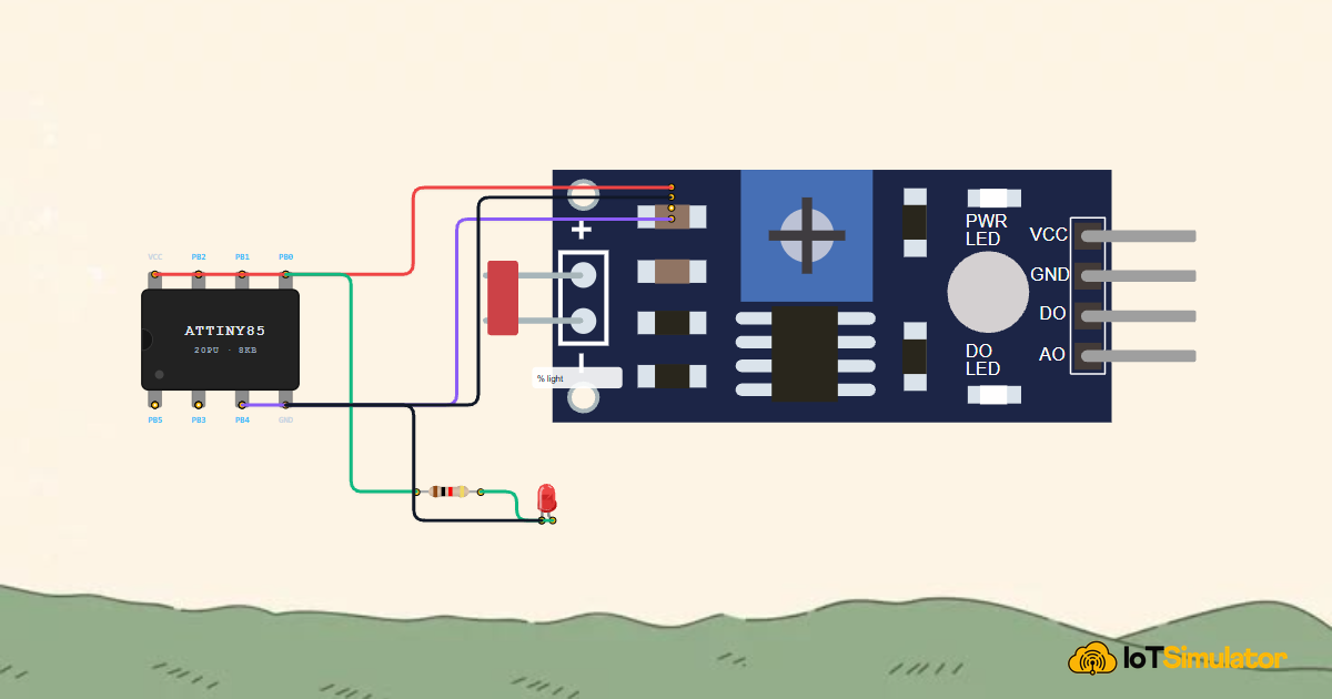
Live project track
Every solar garden light, emergency runway marker, and automatic street lamp shares the same core idea: measure the light level, and when it drops low enough, switch something on. You do not need to touch a button or set a timer — the circuit reads the room and decides on its own. In this project, your ATtiny85 watches a light sensor and slowly fades a red LED to a gentle breathing glow the moment the room goes dark.
In this project, you will connect a photoresistor (LDR) sensor module and a red LED to an ATtiny85 microcontroller. The main idea has two parts: the LDR sensor turns light into a voltage that the chip can read as a number, and the chip uses a technique called PWM to smoothly control how bright the LED is — not just on or off, but anywhere in between.
How the Light Sensor Reads the Room
A photoresistor, also called an LDR (Light Dependent Resistor), is a component whose electrical resistance changes based on how much light hits it. In bright light, its resistance drops very low, which lets more current flow and produces a higher voltage at the sensor's output pin. In darkness, its resistance rises very high, current flow drops, and the output voltage falls. The ATtiny85 reads this voltage through its analog-to-digital converter (ADC), which turns a voltage into a number from 0 (darkest) to 1023 (brightest).
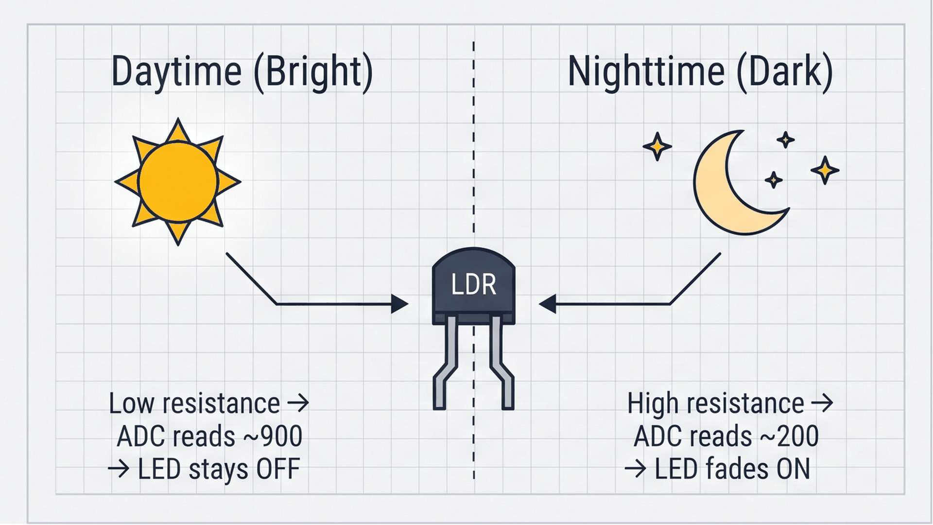
The diagram above shows the two states clearly. During daytime, the sensor reads a high number (around 700–900 depending on your lighting). During nighttime, it reads a low number (around 100–300). Your code checks whether the reading falls below a threshold — in this project, that threshold is 400. Any reading below 400 means the room is dark enough to turn the beacon on.
| Light condition | LDR resistance | ADC reading | LED |
|---|---|---|---|
| Bright sunlight / office light | Low (~1 kΩ) | 700 – 1023 | OFF |
| Dim room / evening | Medium (~10 kΩ) | 350 – 700 | Depends on threshold |
| Dark room / night | High (~100 kΩ+) | 0 – 350 | Fading ON |
You can adjust the DARKNESS_THRESHOLD constant in the code to match your environment. Raise it to 500 or 600 if you want the beacon to turn on earlier in the evening. Lower it to 200 if you only want it active in true darkness.
Controlling Brightness with PWM
An LED can only be fully on or fully off — you cannot dim it by lowering the voltage the way you would with a lamp. Instead, the ATtiny85 uses a trick called Pulse Width Modulation (PWM). It switches the LED on and off hundreds of times per second, so fast that your eye cannot see the individual flashes. What your eye perceives instead is the average brightness: if the LED is on 90% of the time, it looks very bright; if it is on only 10% of the time, it looks very dim.
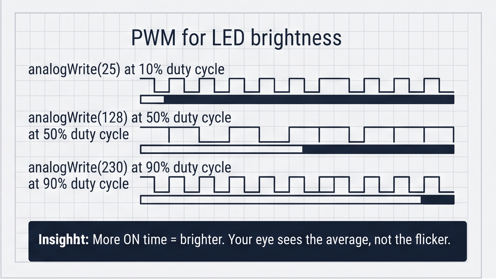
The diagram shows three different pulse patterns. The top row has very short ON pulses (about 10% of each cycle) — the LED looks barely lit. The middle row is 50% ON, which looks like medium brightness. The bottom row is 90% ON, which looks almost fully bright. In Arduino code, you control the PWM duty cycle by calling analogWrite(pin, value) where the value ranges from 0 (always off) to 255 (always on). The breathing fade effect in this project steps through every value from 0 to 255 and back down again, pausing 20 ms between each step.
The ATtiny85 handles PWM automatically using its internal Timer0 hardware. When you call analogWrite(0, 128), the timer takes over and generates the switching pulses on PB0 without needing any code in your loop to manage it.
Connecting the Components
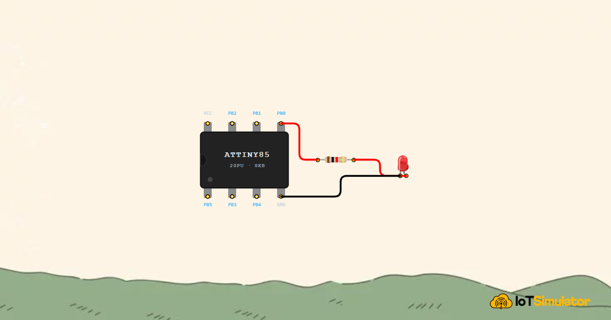
The circuit uses four connections: power and ground to the LDR sensor module, the sensor's analog output signal into PB4 (the ADC pin), and the PWM-capable PB0 driving the LED through a 220Ω resistor. The resistor limits the current through the LED to a safe level, protecting both the LED and the ATtiny85 output pin.
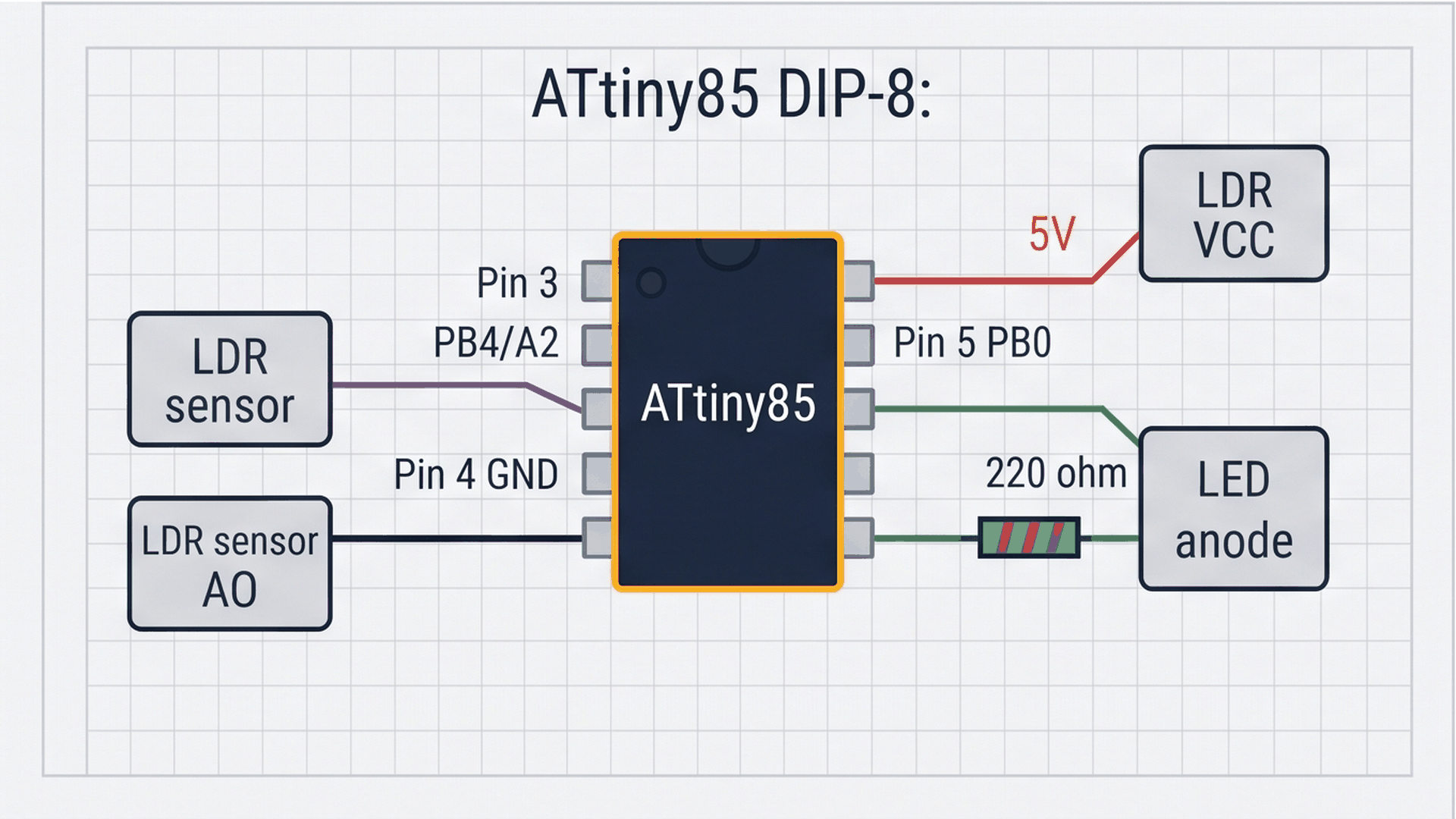
Physical pin 3 on the ATtiny85 is PB4, which is connected to the chip's ADC channel 2 (called A2 in Arduino code). Physical pin 5 is PB0, which is the only PWM-capable pin on the ATtiny85 by default. The 220Ω resistor sits between PB0 and the LED anode to keep current at a safe ~14 mA at full brightness.
Next, connect the LED indicator to physical pin 5 (PB0) through a 220Ω current-limiting resistor to produce the visible beacon pulse:
Notice that PB4 (pin 3) is only used as an analog input here, not a digital output. You do not need to call pinMode() on it — analogRead(A2) configures it automatically as an input when called.
Complete Code
The sketch below is the full program. It checks the light level on every loop cycle. If the room is dark enough, it runs the fade-up and fade-down breathing cycle. If the room is bright, it keeps the LED off and waits 250 ms before checking again — which saves a little power compared to looping as fast as possible.
// ATtiny85 Automatic Night Light
// Reads a light sensor on PB4 (A2) and fades an LED on PB0

const int LDR_PIN = A2; // Physical Pin 3 (PB4)
const int LED_PIN = 0;  // Physical Pin 5 (PB0, supports PWM)

// Below this reading the room is considered dark
const int DARKNESS_THRESHOLD = 400;

void setup() {
  pinMode(LED_PIN, OUTPUT);
  analogWrite(LED_PIN, 0); // start with LED off
}

void loop() {
  // Read how bright the room is (0 = dark, 1023 = very bright)
  int lightLevel = analogRead(LDR_PIN);

  if (lightLevel < DARKNESS_THRESHOLD) {
    // Room is dark — fade the LED up
    for (int b = 0; b <= 255; b += 5) {
      analogWrite(LED_PIN, b);
      delay(20);
    }
    // Then fade it back down
    for (int b = 255; b >= 0; b -= 5) {
      analogWrite(LED_PIN, b);
      delay(20);
    }
  } else {
    // Room is bright — keep LED off
    analogWrite(LED_PIN, 0);
    delay(250);
  }
}
How the Code Works, Part by Part
The sketch is organized into three clear sections: the pin and threshold constants at the top, the setup() that initializes the LED, and the loop() that continuously reads the sensor and decides what to do. Each part has a specific job.
▸ Pin Constants and the Darkness Threshold
The two const int lines give the pins readable names instead of raw numbers. A2 maps to physical pin 3 on the ATtiny85, and 0 maps to physical pin 5. The DARKNESS_THRESHOLD constant is the key tuning value — it separates what your code considers day from what it considers night. Changing this one number adjusts when the beacon activates without touching anything else.
const int LDR_PIN = A2; // Physical Pin 3 (PB4)
const int LED_PIN = 0;  // Physical Pin 5 (PB0, supports PWM)

const int DARKNESS_THRESHOLD = 400;
If your room reads around 450 even with the lights off, raise the threshold to 550. If the beacon turns on in normal indoor lighting, lower the threshold to 300. The right value depends on your specific LDR module and environment.
▸ The Breathing Fade Loops
Inside the dark condition, two for loops create the breathing effect. The first loop counts b from 0 to 255 in steps of 5, calling analogWrite(LED_PIN, b) at each step with a 20 ms pause. This takes about one second to go from completely off to fully bright. The second loop counts back down from 255 to 0 in the same way, fading the LED back to dark over another second.
// Fade up
for (int b = 0; b <= 255; b += 5) {
  analogWrite(LED_PIN, b);
  delay(20);
}
// Fade down
for (int b = 255; b >= 0; b -= 5) {
  analogWrite(LED_PIN, b);
  delay(20);
}
You can adjust the fade speed by changing the step size and delay. Smaller steps with shorter delays make the fade smoother and faster. Larger steps with longer delays make it slower and more dramatic. For example, b += 1 with delay(8) gives a very smooth 2-second fade.
▸ Daytime Idle Mode
When the light level is above the threshold, the LED is turned off with analogWrite(LED_PIN, 0) and the code waits 250 ms before checking again. This short idle pause reduces how often the ATtiny85 samples the ADC and runs the loop, which saves a small amount of power during the day when nothing needs to happen.
} else {
  // Room is bright — keep LED off
  analogWrite(LED_PIN, 0);
  delay(250);
}
The analogWrite(LED_PIN, 0) call is important here. If the power were cut to the LED mid-fade, the PWM output might hold whatever duty cycle it was last set to. Explicitly writing 0 guarantees the LED is completely off every time the room is detected as bright.
Fixing Common Problems
If the beacon does not behave as expected, the table below covers the most likely causes.
| What you see | Likely cause | What to try |
|---|---|---|
| LED stays on even in bright light | Threshold too high or LDR wired to wrong pin | Check the purple wire is on PB4 (pin 3); lower DARKNESS_THRESHOLD to 300 |
| LED never turns on even in darkness | Threshold too low, LED polarity reversed, or missing 220Ω resistor | Confirm LED anode faces resistor, cathode faces GND; raise threshold to 550 |
| LED jumps abruptly instead of fading | digitalWrite() used instead of analogWrite() | Make sure the code uses analogWrite(LED_PIN, b) inside the fade loops |
| LED keeps flickering on and off rapidly | Light sensor reading hovering right at the threshold | Move the LDR away from the LED so it does not detect its own light; adjust threshold |
The most common issue is the LDR detecting the LED's own glow. If the LED and sensor are facing each other on a small breadboard, the LED light bounces back and raises the LDR reading, which turns the LED off, which lowers the reading, which turns it on again — and the loop flickers. Pointing the sensor away from the LED fixes it instantly.
Try It in the Simulator
Click Start Simulation (▶) in the toolbar. The light sensor on the canvas starts at a default brightness level. Adjust the sensor value down to simulate darkness and watch the LED fade on with a smooth breathing rhythm. Raise the value back up to simulate daylight and the LED will quietly fade off. Try changing DARKNESS_THRESHOLD in the code to see how the trigger point shifts.
More in ATtiny85
More in Sensors
Build a Smart Climate Monitor with a Raspberry Pi Pico W
Build a Light Meter and Alarm with a Raspberry Pi Pico
Build a Multi-Room Safety Monitor with an Arduino Mega
Build a Motion Security Chime with an Arduino Nano
Build an Automatic Night Light with an Arduino Nano
More in Lighting
More in Beginner
Build a 4-Key Piano Synthesizer with a Raspberry Pi Pico W
Control a Servo Positioner with a Raspberry Pi Pico
Build a Light Meter and Alarm with a Raspberry Pi Pico
Build a Motion Security Chime with an Arduino Nano