Control a Servo with an ESP32-C3 and Potentiometer

Live project track
Steering a robotic arm, aiming a pan-and-tilt camera, or controlling a throttle lever all share the same requirement: moving a motor to an exact angle and holding it there. Standard motors spin continuously without stopping, but a servo motor rotates to the precise position you command and locks in place.
In this project, you will build an interactive servo steering system using an ESP32-C3 microcontroller, a 10k rotary potentiometer, and an SG90 micro servo. The main idea is that the potentiometer acts as a physical steering dial, the ESP32-C3 reads its analog voltage with 12-bit precision, and the code outputs microsecond timing pulses on GPIO 3 to position the servo arm in real time.
Mapping Knob Movement to Motor Angles
A potentiometer is an adjustable voltage divider. As you turn the dial from left to right, the voltage on its middle pin slides smoothly between 0.0V and 3.3V. The ESP32-C3 converts this analog signal into a digital number using its 12-bit analog-to-digital converter (ADC), producing a range of 4096 individual steps from 0 to 4095.
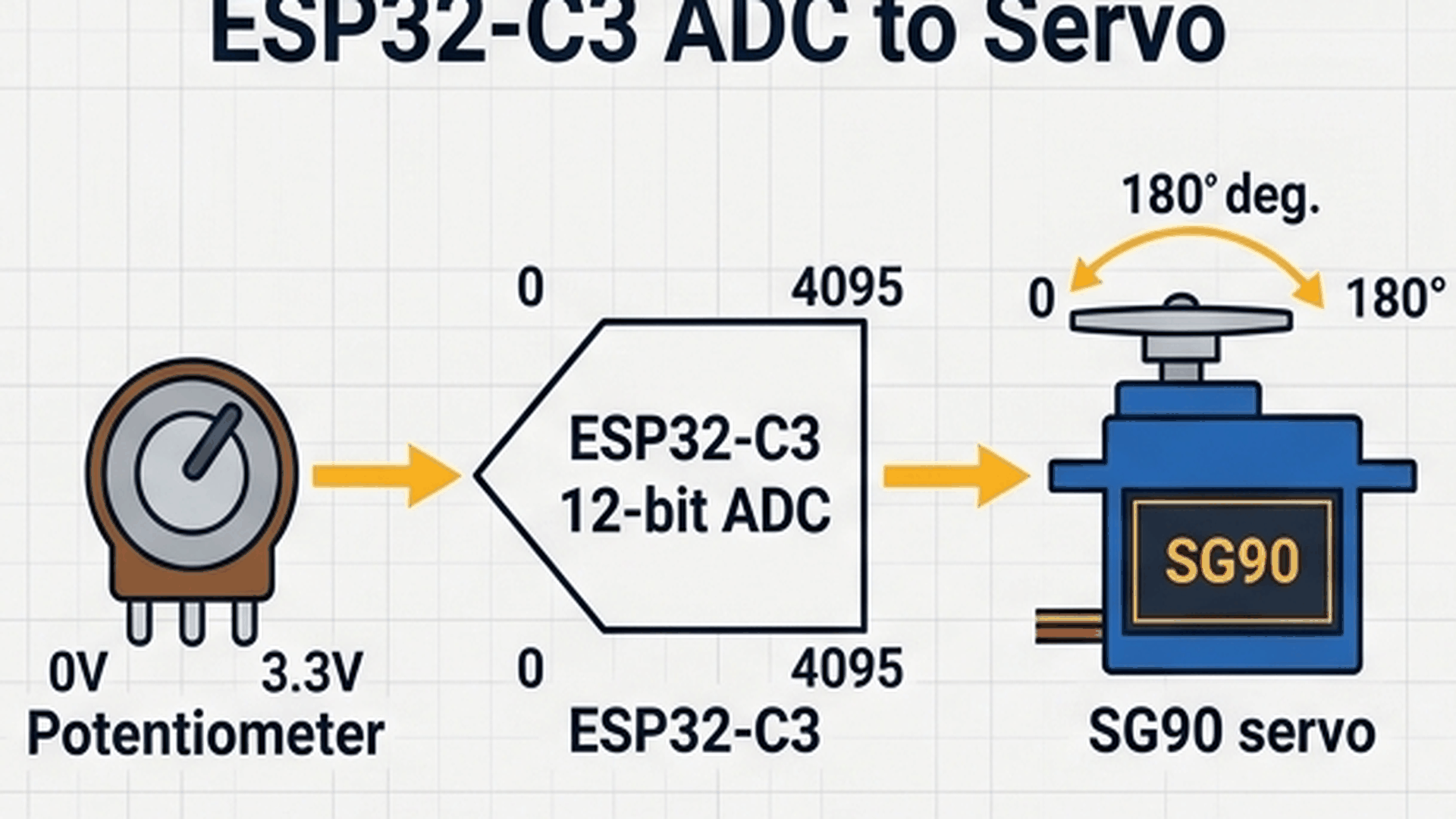
The diagram above illustrates the signal flow. The raw 0–4095 reading maps directly to target angles between 0° and 180°. A dedicated helper function then translates that angle into the exact microsecond pulse duration required by the motor. As you turn the dial, the servo mirrors your hand movements immediately.
| Knob position | Wiper voltage | ADC reading (0–4095) | Target angle | Pulse duration |
|---|---|---|---|---|
| Full counter-clockwise | 0.00 V | 0 | 0° (Left) | 544 µs |
| Halfway turned | 1.65 V | ~2048 | 90° (Center) | 1500 µs |
| Full clockwise | 3.30 V | 4095 | 180° (Right) | 2400 µs |
Because the ESP32-C3 offers 12-bit resolution (4096 steps) compared to an older 10-bit Arduino Uno (1024 steps), the analog reading is four times as fine, ensuring smooth angular transitions without step stuttering.
How the Servo Interprets Pulse Timing
A hobby servo motor does not respond to raw voltage levels. Instead, an internal motor driver board measures the duration of repeated high pulses sent every 20 milliseconds (a 50Hz repetition rate). The width of each high pulse tells the motor which angle to hold.
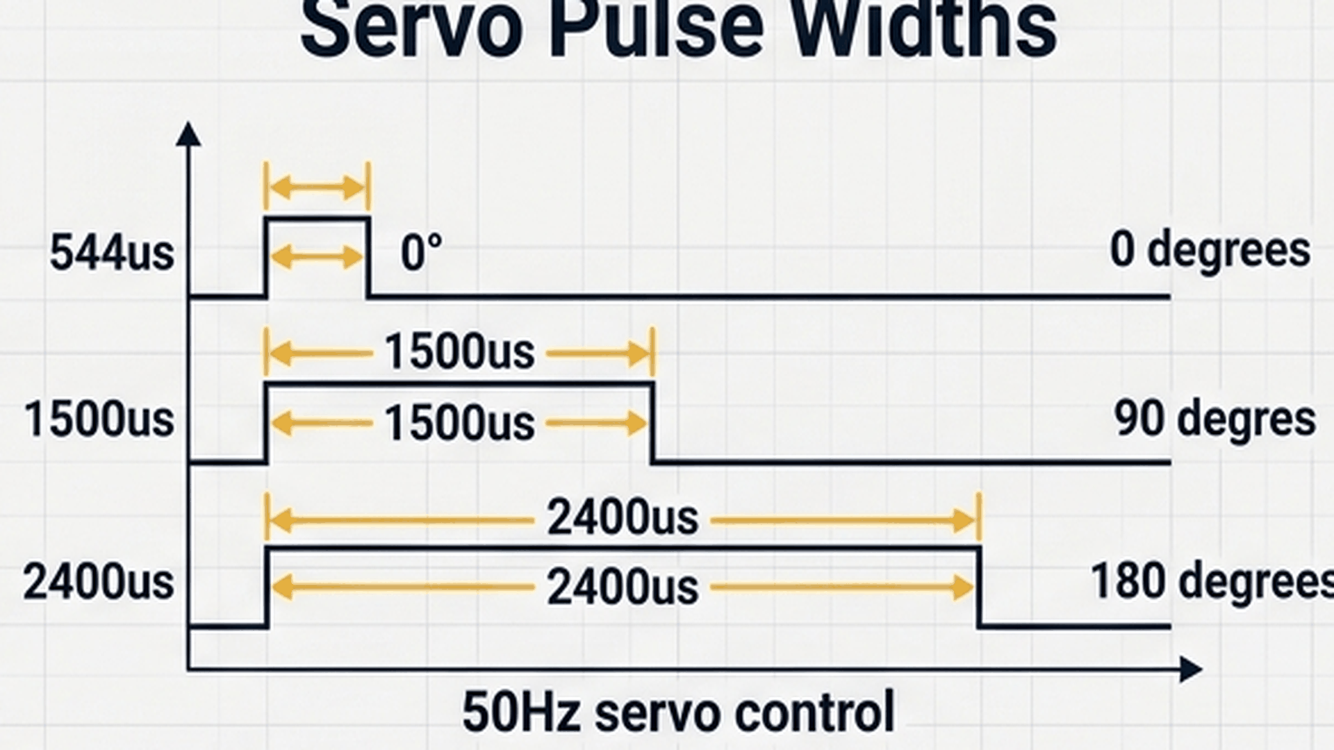
The waveform diagram above shows the standard pulse widths used by the TowerPro SG90 servo. A short pulse of 544 microseconds commands the horn to full left (0°). A pulse of 1500 microseconds commands neutral center (90°). A long pulse of 2400 microseconds commands full right (180°).
| Servo horn orientation | Pulse width (microseconds) | Pulse width (milliseconds) | Frame frequency |
|---|---|---|---|
| 0° (Full Left) | 544 µs | ~0.54 ms | 50 Hz (20 ms period) |
| 90° (Neutral Center) | 1500 µs | 1.50 ms | 50 Hz (20 ms period) |
| 180° (Full Right) | 2400 µs | 2.40 ms | 50 Hz (20 ms period) |
Delivering these pulses at a steady 50Hz rate provides the servo with continuous power and holding torque, keeping the arm firmly at its commanded position even when external physical resistance is applied.
Connecting the Circuit
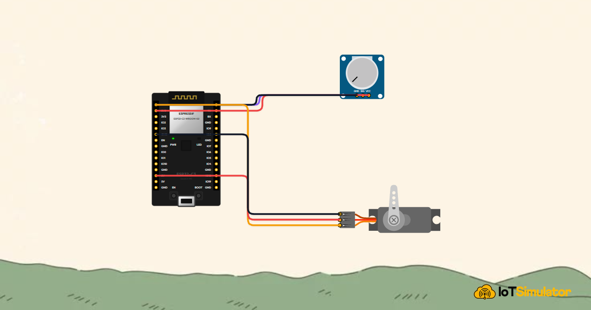
Connecting a knob to a servo motor creates a direct steering link — just like the steering wheel of a car directing the front wheels. When you turn the knob left, the motor points left; when you center the knob, the motor stands straight.
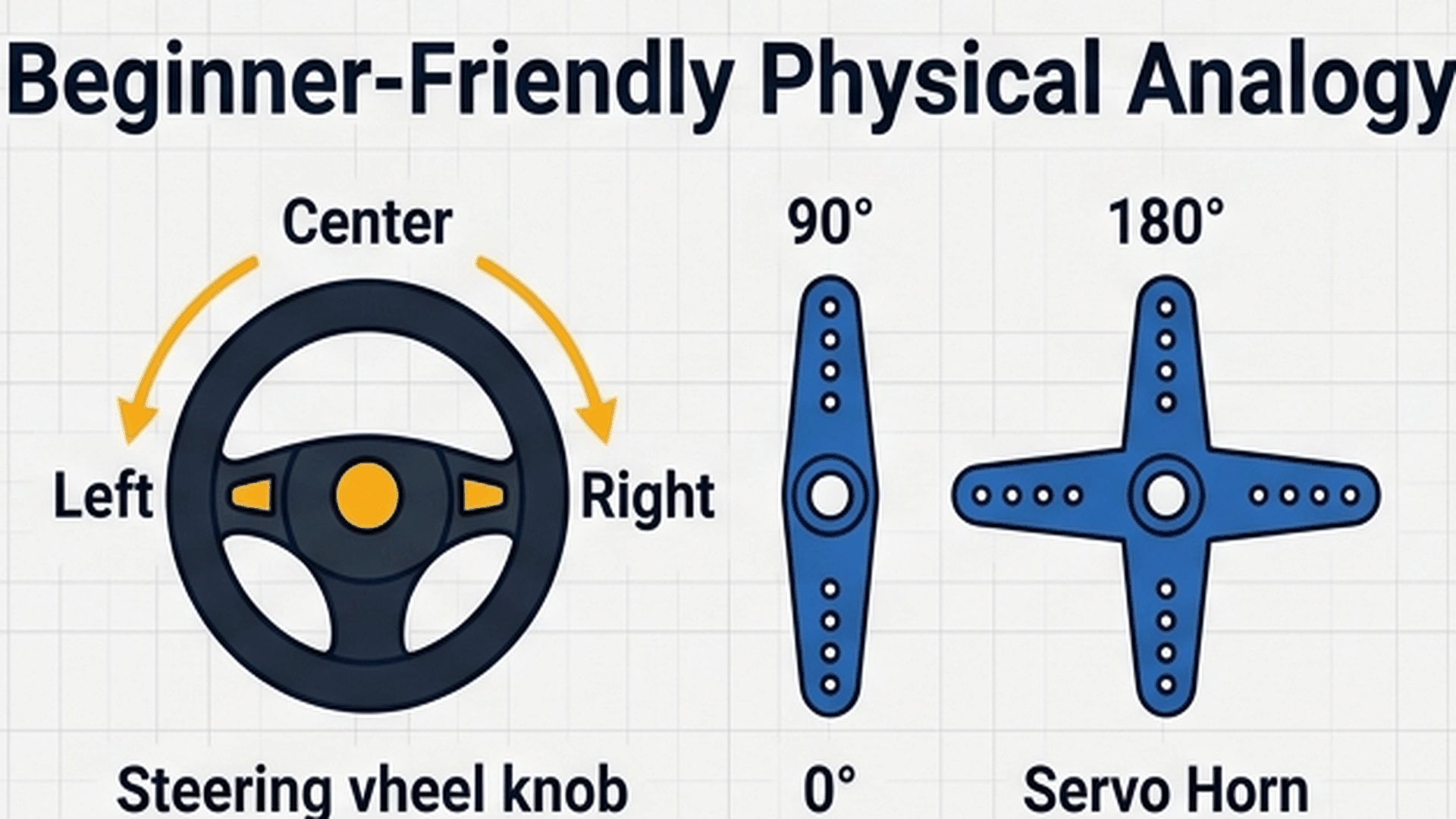
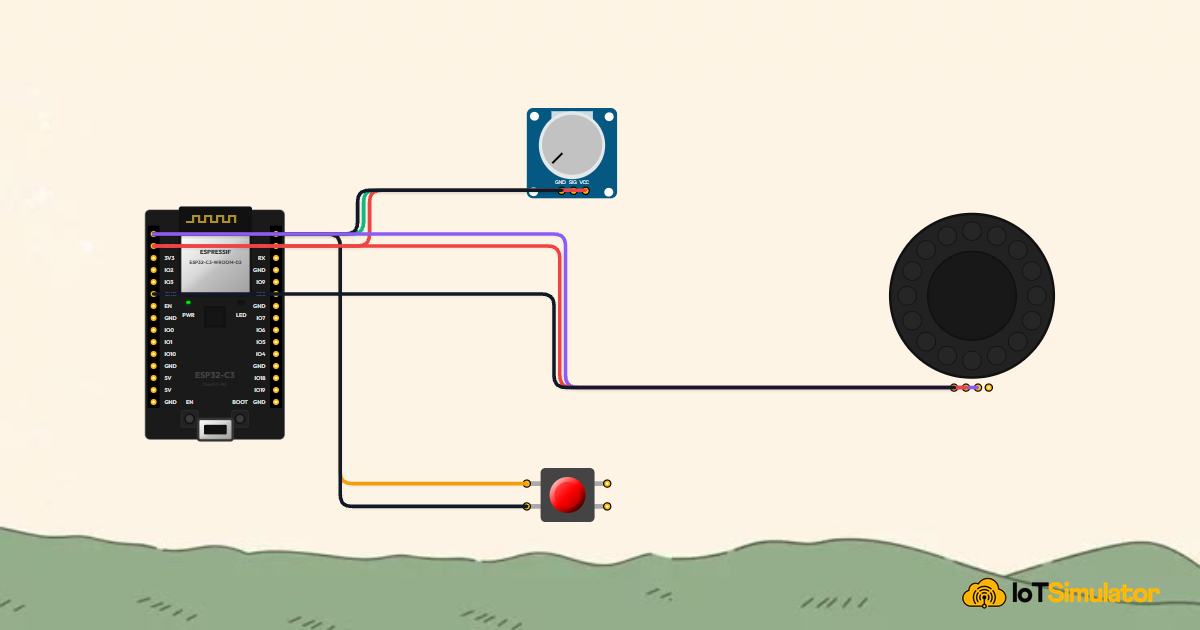
As shown in the illustration, the microcontroller acts as the steering column, translating analog knob positions into exact degree commands. Connect the potentiometer and servo as detailed below:
Next, connect the TowerPro SG90 micro servo control wire to GPIO 2 to receive high-precision 50Hz PWM position commands:
Notice the power rail separation: the potentiometer uses 3.3V because ESP32-C3 analog inputs cannot tolerate voltages above 3.3V. The servo motor, however, connects to the 5V pin because its internal DC motor requires 5V for full torque and movement speed.
Complete Code
Upload the following sketch to your ESP32-C3 DevKit. It samples the potentiometer, computes the target angle, transmits precision microsecond pulses to GPIO 3, and streams live telemetry to the serial monitor.
// ============================================================================
// ESP32-C3 RISC-V: Precision ADC Analog Reading & Servo Position Control
// Potentiometer Signal -> GPIO 0 (ADC1_CH0)
// SG90 Servo PWM       -> GPIO 3
// ============================================================================

const int POT_PIN = 0;
const int SERVO_PIN = 3;

// Precision microsecond pulse generator for SG90 servo
void setServoAngle(int pin, int angle) {
  // SG90 standard timing: 0 deg = 544us, 180 deg = 2400us
  int pulseWidthUs = map(angle, 0, 180, 544, 2400);
  digitalWrite(pin, HIGH);
  delayMicroseconds(pulseWidthUs);
  digitalWrite(pin, LOW);
}

void setup() {
  Serial.begin(115200);
  delay(200);

  pinMode(POT_PIN, INPUT);
  pinMode(SERVO_PIN, OUTPUT);
  digitalWrite(SERVO_PIN, LOW);

  Serial.println(F("==========================================="));
  Serial.println(F(" ESP32-C3 Potentiometer & Servo Controller "));
  Serial.println(F(" ADC Resolution: 12-bit (0 - 4095)         "));
  Serial.println(F(" Servo Range: 0 - 180 Degrees              "));
  Serial.println(F("==========================================="));
}

void loop() {
  // 12-bit ADC reading (0 to 4095 corresponding to 0V - 3.3V)
  int rawADC = analogRead(POT_PIN);
  float voltage = (rawADC / 4095.0f) * 3.3f;
  int targetAngle = map(rawADC, 0, 4095, 0, 180);

  // Transmit 50Hz refresh pulse to servo
  setServoAngle(SERVO_PIN, targetAngle);

  // Telemetry output
  Serial.print(F("[ADC: "));
  Serial.print(rawADC);
  Serial.print(F(" | "));
  Serial.print(voltage, 2);
  Serial.print(F("V] -> Target Angle: "));
  Serial.print(targetAngle);
  Serial.println(F(" deg"));

  // Servo 50Hz frame timing (approx 20ms period)
  delay(20);
}
How the Code Works, Part by Part
The program uses clean, standalone C++ logic without requiring third-party servo libraries. Here is what happens in each section of the code.
▸ Pin Assignments and the Pulse Generator Helper
At the top of the sketch, the code defines the pins and creates the setServoAngle() helper function.
const int POT_PIN = 0;
const int SERVO_PIN = 3;

void setServoAngle(int pin, int angle) {
  int pulseWidthUs = map(angle, 0, 180, 544, 2400);
  digitalWrite(pin, HIGH);
  delayMicroseconds(pulseWidthUs);
  digitalWrite(pin, LOW);
}
The helper maps the desired angle (0°–180°) into microseconds (544µs–2400µs), turns the pin HIGH, waits for that duration using delayMicroseconds(), and sets the pin back to LOW.
▸ Initializing Pins and Serial Output in setup()
Inside setup(), the microcontroller configures the pin modes and initializes the USB serial connection at 115200 baud.
pinMode(POT_PIN, INPUT);
pinMode(SERVO_PIN, OUTPUT);
digitalWrite(SERVO_PIN, LOW);
Setting SERVO_PIN to LOW prevents spurious pulses from triggering the motor during the board's startup sequence.
▸ Reading the Knob and Updating the Servo in loop()
The loop() function reads the instantaneous potentiometer value, maps it to an angle, and transmits the pulse.
int rawADC = analogRead(POT_PIN);
float voltage = (rawADC / 4095.0f) * 3.3f;
int targetAngle = map(rawADC, 0, 4095, 0, 180);

setServoAngle(SERVO_PIN, targetAngle);
delay(20);
The delay(20) call at the bottom pauses for 20 milliseconds, matching the standard 50Hz frame rate required by hobby servos.
Fixing Common Problems
If the motor does not turn or behaves erratically, check the common solutions below.
| What you see | Likely cause | What to try |
|---|---|---|
| Servo does not turn at all | Motor wired to 3.3V instead of 5V or wrong pin | Verify servo power wire connects to 5V.1 and PWM signal wire to GPIO 3 |
| ESP32-C3 resets or restarts when knob is turned | Motor drawing too much current from USB port | Add a 100µF capacitor across 5V and GND near the servo, or use an external 5V supply |
| Servo moves in the opposite direction of knob | Potentiometer VCC and GND wires swapped | Swap the outer power and ground connections on the potentiometer |
| Servo only travels across ~90 degrees | Non-standard servo timing thresholds | Adjust pulse bounds in setServoAngle() from 544, 2400 to 500, 2500 |
When moving rapidly, physical servo motors can momentarily draw significant current. Powering the servo from the 5V rail rather than the 3.3V pin protects the ESP32-C3's internal regulator from brownout resets.
Try It in the Simulator
Click the Start Simulation (▶) button in the top toolbar to begin. Click and drag the rotary dial on the Potentiometer on the canvas. Watch the SG90 Servo arm track the dial smoothly in real time across the complete 180-degree arc, while the Serial Monitor tab streams live angle readings!