If you have ever played with classic 8-bit boards like the Arduino Uno, picking up a Raspberry Pi Pico feels like stepping into a modern sports car. At just a few dollars, it packs a dual-core 32-bit ARM Cortex-M0+ processor running at a snappy 133 MHz, paired with 26 multi-function GPIO pins. It has enough speed and memory to run complex calculations, yet it remains simple enough to wire up on a small desktop breadboard in minutes.
In this guide, we walk you through 5 hands-on starter projects. Instead of getting stuck reading long code printouts, you can see and interact with every circuit right in your browser. Feel free to click Run Simulation on each preview below, tinker with the dials and sensors, and click Fork in Simulator whenever you want to adapt the circuit for your own creations.
Essential Hardware Habits for the RP2040
Before you start running jumper wires across your board, there are a few hardware differences between the Pico and older maker boards that are worth knowing:
- Strict 3.3V Logic Levels: Unlike classic 5V Arduino boards, the Pico runs its GPIO pins at 3.3V. Feeding a 5V signal directly into an input pin can permanently damage your board. Always make sure your sensor outputs stay within 3.3V, or use a level converter when dealing with older 5V modules.
- Pin 36 (3V3 Out) vs Pin 40 (VBUS): Pin 36 gives you clean, regulated 3.3V power straight from the onboard power supply chip, ideal for sensitive sensors and screens. Pin 40 (VBUS), on the other hand, routes raw 5V power directly from your micro-USB cable. That makes VBUS the perfect place to tap power for motors and servos without overloading the Pico's 3.3V regulator.
- Plentiful Ground Pins: Take a look at the pinout diagram and you will spot 8 distinct ground pads, each marked with a small square border. This means you rarely need to cram multiple black ground wires into one corner of your breadboard.
- Onboard Green LED: The board has a built-in green LED connected to pin GP25, giving you a quick way to test if your sketch is alive without touching a single external resistor.
Three Features That Make the Pico Shine
As you explore the projects below, you will notice three key capabilities of the RP2040 chip that make working with it a delight:
- 12-bit Analog Conversion (ADC): Standard microcontrollers often slice analog voltages into 1,024 levels (10 bits). The Pico gives you 4,096 levels (12 bits), making sensor readings much smoother and far more accurate.
- Dedicated Hardware PWM Slices: Generating pulse signals for motors or servos can tie up a processor. The RP2040 features built-in hardware PWM generators that keep signals perfectly timed in the background without dropping a beat.
- Native I2C Serial Buses: Instead of tying up eight or ten pins just to draw characters on a screen, the Pico communicates with displays using just two communication wires (SDA and SCL).
1. External Dual LED Status Indicator
Every maker starts by blinking a light, but in real gadgets—like factory machines, 3D printers, and network routers—LEDs are used to communicate machine health. A steady green pulse tells you everything is running smoothly, while a quick red flash signals that an error needs attention.
In this project, we step beyond the onboard GP25 light by wiring two external LEDs on a breadboard. The red LED hooks up to pin GP14 and the green LED goes to GP15. Notice that each LED passes through its own 220-ohm resistor before meeting ground. Skipping this resistor would let too much current flow through the diode, which could quickly burn out both the LED and your Pico pin.
When you start the circuit, the Pico creates an alternating heartbeat: the green indicator pulses on and off, followed by the red alert lamp. It is a simple circuit, but it lays the groundwork for how status signals work in almost every embedded device.
Try it in the simulator: Click Run Simulation to see the green and red lamps alternate. Once you see it working, click Fork in Simulator and try shortening the delay in the sketch to turn the alternating pulse into an urgent warning flash.
Digital outputs like LEDs are either fully on or fully off. But how does a microcontroller listen to the analog real world, where temperatures and light levels are always shifting gradually?
2. Smart Light Meter Alarm (12-Bit ADC + Buzzer)
Whether you are building an automatic greenhouse monitor, an astronomy camera guard, or a nightstand clock, you often need to detect when room lighting drops below a safe threshold. This project shows how easy it is to pair an analog photoresistor with an acoustic alarm.
We set up a classic voltage divider: one leg of a light-dependent resistor (LDR) connects to the 3.3V rail, while the other leg meets a 10k fixed resistor connected to ground. The junction point between them runs straight into pin GP26, which serves as the Pico's first analog channel (ADC0). When shadows fall over the sensor, its electrical resistance shoots up, changing the voltage that reaches pin GP26.
Because the RP2040 reads this voltage in 4,096 distinct steps, it can spot tiny variations in room brightness. When the reading crosses our darkness threshold, the Pico sounds a chirping tone on a piezo buzzer connected to GP16.
Try it in the simulator: Start the simulation and grab the light slider on the photoresistor component. Slide it toward the dark side and listen as the piezo buzzer begins chirping. Slide it back toward the bright side and watch the alert silence itself immediately.
An audio beep is great for urgent warnings, but what if you want to inspect exact numbers, check live humidity percentages, or view temperature graphs?
3. Environmental OLED Weather Dashboard (DHT22 + I2C)
Wiring an old-school display with ten parallel ribbon cables can quickly turn your breadboard into a bird's nest. Modern electronics solve this with serial buses like I2C, which allow microcontrollers to drive rich graphic screens using just two shared communication lines.
In this project, we pair a high-contrast 128x64 SSD1306 OLED screen with a calibrated DHT22 temperature and humidity sensor. The OLED uses two communication pins: GP4 acts as the SDA data line, while GP5 acts as the SCL clock signal. Both parts receive clean 3.3V power from pin 36. Meanwhile, the DHT22 streams digital climate packets directly into pin GP15.
Every two seconds, the Pico asks the sensor for fresh measurements, formats the data, and draws a clean digital readout on the screen. Because OLED pixels emit their own light, the screen stays readable from wide angles while sipping only a few milliamps of current.
Try it in the simulator: Run the simulation and drag either the temperature or humidity slider on the white DHT22 sensor module. Within a couple of seconds, the live digital numbers on the OLED screen update to mirror your adjustments.
Now that we have explored sensors and graphical screens, let us add physical movement to our circuits and see how the Pico drives robotic motors with precision.
4. Micro Servo Dial Controller (Hardware PWM)
Have you ever seen a cheap hobby servo twitch randomly or make an annoying humming sound while sitting still? That usually happens when a microcontroller gets distracted by other tasks and lets its timing pulses drift. Hobby servos expect very precise electrical pulses every 20 milliseconds (a 50 Hz rhythm), where pulse widths between 1 and 2 milliseconds dictate the exact horn angle.
The Raspberry Pi Pico eliminates jitter entirely by using dedicated hardware PWM slices. Once you tell the Pico what angle you want, the internal hardware counter handles the timing pulses automatically, freeing up the CPU completely.
In this circuit, a 10k rotary dial connects between 3.3V and ground with its wiper pin hooked to GP26 (ADC0). The servo signal lead connects to GP16. Notice how the servo power lead routes to VBUS (Pin 40). Servos pull sudden surges of electrical current when their gears turn. By pulling power directly from the 5V USB line instead of the Pico's 3.3V logic supply, your microcontroller never experiences sudden power dips or resets.
Try it in the simulator: Start the engine and rotate the potentiometer knob with your mouse. Notice how the black servo horn glides smoothly from 0 to 180 degrees in real time, tracking the dial position with zero wobble.
What happens when you want to put all these skills together—combining character displays, tactile buttons, analog sensors, and visual indicators into one coordinated system?
5. Multi-Peripheral I2C LCD & Sensor Station
Real-world gadgets rarely rely on just one sensor or display. An intelligent thermostat, for example, needs to read light, monitor buttons, update a screen, and illuminate status LEDs all at the same time. The Raspberry Pi Pico handles this kind of multi-peripheral coordination with ease.
This station connects a 16x2 alphanumeric LCD over the shared I2C bus (GP4 SDA and GP5 SCL), an analog photoresistor on GP26, a tactile push button on GP17, and a green indicator LED on GP16. Notice that the button connects directly between GP17 and ground without an external pullup resistor. We configure the Pico's internal pullup circuitry in software, keeping our component count minimal and our wiring clean.
The Pico monitors both the light level and the button state continuously. If room brightness dips or if you press the manual button, the green status lamp illuminates. At the same time, the LCD screen updates continuously to report the live light level and button status without slowing down.
Try it in the simulator: Click Run Simulation and watch the LCD welcome screen initialize. Drag the photoresistor light slider to watch the live number change, or click the momentary pushbutton to see the status switch immediately on the screen.
Taking Your Next Steps with the Pico
From gentle alternating status indicators and 12-bit analog light meters to sharp OLED weather screens, steady servo motor controls, and multi-sensor stations, the Raspberry Pi Pico makes electronics prototyping fast, reliable, and fun.
The best way to learn is by doing. Click Fork in Simulator on any of the circuits above to open it in your personal workspace. You can change pin assignments, tweak threshold values, or add new components with complete freedom. Everything runs safely in the cloud, so you can experiment without any risk of damaging physical parts.
Related Projects & Circuits
Explore more working circuits with code and simulations pre-assembled.
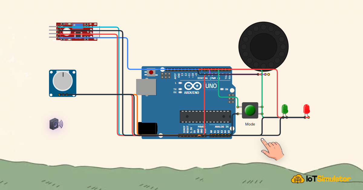
WS2812 NeoPixel Ring Music VU Meter & Sound Visualizer
6 ATtiny85 Projects for Beginners
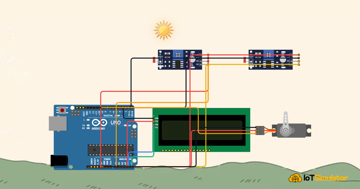
Arduino Single-Axis Solar Tracker with Dual LDRs and Servo
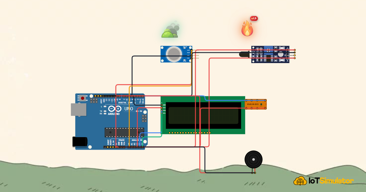
Arduino Fire Alarm & Gas Leak Detector with Siren and Relay
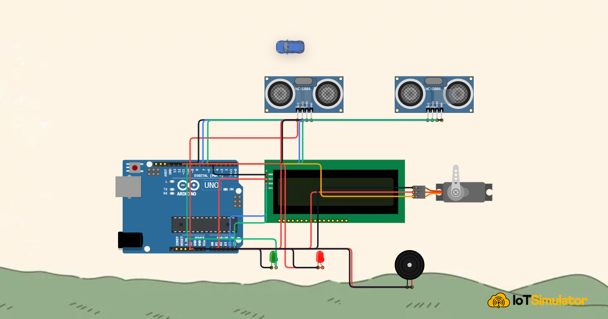
Arduino Smart Parking Barrier & Slot Counter with Ultrasonic Sensor