
Big boards like the Arduino Mega or Raspberry Pi are fantastic when you need dozens of pins and heavy computation. But when you want to build a tiny bike safety flasher, an automatic jewelry box lamp, or a battery-powered garden sensor, using a full-sized development board is like driving an 18-wheeler truck to the corner grocery store.
That is where the ATtiny85 comes in. Inside an 8-pin plastic package no larger than a fingernail sits a complete 8-bit AVR microcomputer with 8 KB of flash program memory, 512 bytes of SRAM, and 6 versatile input/output pins. It operates reliably between 2.7V and 5.5V, making it the gold standard for projects powered by simple 3V coin cells or small rechargeable batteries.
In this guide, we explore 6 practical beginner projects that showcase what this little chip can do. You do not need to hunt down special programmer clips or install desktop drivers: every circuit below includes an interactive virtual breadboard that you can run, test, and adapt directly in your browser.
Why Makers Love the ATtiny85
Working with an ultra-compact chip is a refreshing experience for any electronics enthusiast:
- Tiny Footprint: Measuring just under 10 mm in length, the dual-in-line package fits on tiny breakout boards or directly inside wearable gear without adding bulk.
- Extreme Battery Life: In sleep mode, an ATtiny85 can draw less than 5 microamps. A single CR2032 coin cell can keep a sensor alive for months or even years.
- Fewer Distractions: With just 6 GPIO pins to manage, wiring stays neat and circuit debugging becomes straightforward.
- True Embedded Mindset: Learning how to get the most out of 512 bytes of memory sharpens your coding skills and teaches you to write efficient, responsive code.
ATtiny85 Pinout Quick Reference
Because the chip has only 8 physical legs, understanding which pin does what is essential before you plug in your wires:
- Pin 8 (VCC): Connects to DC power (typically 3V to 5V).
- Pin 4 (GND): Connects to common system ground (0V).
- Pin 5 (PB0): Digital Input/Output, PWM timer output. Perfect for LEDs and servos.
- Pin 6 (PB1): Digital Input/Output, PWM timer output.
- Pin 7 (PB2): Digital Input/Output, Analog Input (ADC1), and I2C SCL clock line.
- Pin 2 (PB3): Digital Input/Output, Analog Input (ADC3).
- Pin 3 (PB4): Digital Input/Output, Analog Input (ADC2).
- Pin 1 (PB5): Configured as the chip reset pin by default, so we leave it unassigned in everyday projects to avoid accidental resets.
1. Basic LED Blink (Hello World)
Every maker journey begins with the classic blink sketch. On an ATtiny85, seeing an external light turn on and off for the first time is special because there are no USB chips or power regulators between you and the bare silicon.
We connect a 220-ohm current-limiting resistor from digital pin PB0 (physical pin 5) to the anode of a red LED, and route the cathode back to ground (physical pin 4). When the chip powers up, it alternates pin PB0 between HIGH and LOW once every second.
This minimal setup forms the building block for compact optical indicators, beacon flashers, and illuminated art badges.
Try it in the simulator: Press Run Simulation to see the red LED pulse steadily. Click Fork in Simulator to open the code and try changing the delay times to create quick stroboscopic bursts.
Now that we have verified digital outputs, let us explore the ATtiny85's built-in analog converter to react to changes in ambient room light.
2. Automatic Night Light (LDR Sensor)
Ever wanted a porch light, closet lamp, or nightlight that turns itself on automatically as the sun sets? An ATtiny85 handles this task without needing any complex external timers.
We create a simple voltage divider using a photoresistor (LDR) and a 10k fixed resistor, tapping the midpoint voltage into analog pin PB2 (physical pin 7). When bright light shines on the photoresistor, its electrical resistance drops, lowering the voltage. When dusk falls and shadows cover the sensor, its resistance jumps up.
The ATtiny85 measures this analog signal using its internal 10-bit analog-to-digital converter (giving numbers from 0 to 1,023). When the reading crosses our darkness threshold, the chip turns on an indicator LED on pin PB0.
Try it in the simulator: Start the circuit and drag the ambient light slider on the photoresistor toward darkness. Watch the LED switch on as soon as the threshold is reached. Slide it back toward the bright side to see the lamp shut off automatically.
Light sensors can guard our rooms, but how can an ATtiny85 help in an emergency when you need to send a clear distress call across a distance?
3. Morse Code SOS Emergency Beacon
In backcountry hiking, marine safety, or emergency kits, having a lightweight optical flasher that sends a recognized distress signal can be life-saving. The classic Morse code SOS pattern—three quick dots, three long dashes, and three quick dots—is understood worldwide.
This circuit connects a high-visibility yellow LED and a 220-ohm resistor to pin PB0. Rather than using messy nested delay calls, the program uses clean helper functions to pulse the LED with precise international Morse timings: short 200 ms flashes for dots, 600 ms flashes for dashes, and crisp gaps between letters.
Because the chip draws minimal power, an SOS flasher like this can operate off a single pocket-sized battery for days of continuous rescue signaling.
Try it in the simulator: Click Run Simulation and observe the rhythm: three fast flashes (S), three long flashes (O), and three fast flashes (S), followed by a calm pause before repeating. Fork the sketch to spell out your own initials in Morse code.
We have made lights blink, react, and signal messages. Next, let us make something physically move by controlling a mechanical servo motor.
4. Micro Servo Dial Controller
Hobby servo motors are widely used in model planes, robot hands, and miniature camera pans. Servos expect a 50 Hz pulse stream where the width of each pulse (between 1,000 and 2,000 microseconds) dictates the exact angle of the shaft.
Because standard servo libraries are often too bulky for the ATtiny85's modest memory, we generate clean timing pulses using a lightweight software loop. A 10k rotary potentiometer connects to analog pin PB2, allowing you to choose any desired position.
The ATtiny85 reads the knob position, calculates the corresponding pulse width, and sends the signal out on pin PB0. Notice that the servo power leads connect to clean DC power, keeping the motor current from disturbing the chip's internal logic.
Try it in the simulator: Run the simulation and rotate the potentiometer dial with your mouse. Watch the black servo arm track your hand smoothly across its full range of motion.
Servos bring mechanical movement to your projects. Now let us look at user interaction: how to build an intuitive toggle switch with built-in debouncing.
5. Pushbutton Toggle Memory Switch
Have you ever clicked a cheap flashlight button and noticed that it occasionally skips or flickers? Real mechanical push buttons contain tiny metal springs that physically bounce against each other for a few milliseconds when pressed. To a fast microcontroller, a single click can look like ten separate presses in an instant.
This project pairs a tactile push button on pin PB2 with an LED on pin PB0. We enable the ATtiny85's internal pullup resistor, so the pin stays safely HIGH until the button presses it down to ground—saving you an extra external resistor on your breadboard.
The software includes a small debounce timer: once a press is detected, it ignores rapid jitter and toggles the lamp state cleanly. Click once, the light turns on and stays on. Click again, and the light switches off.
Try it in the simulator: Click Run Simulation, then click the momentary push button. Notice how each click cleanly changes the LED state from on to off without any missed triggers or erratic double-clicks.
Finally, let us explore safety alarms by combining analog measurement with an acoustic alert siren to guard temperature-sensitive equipment.
6. Overheat Temperature Alert Siren
Lithium battery charging stations, 3D printer enclosures, and power supply boxes all risk component damage or fire if heat builds up unnoticed. A compact standalone alarm that squeals before things get critical can save valuable equipment.
In this circuit, an analog temperature sensor monitors heat levels on pin PB2, while a piezo buzzer connects to digital pin PB0. When ambient temperatures remain safe, the chip stays silent, sipping virtually zero current.
As soon as heat rises past our safety limit, the ATtiny85 triggers a dual-tone warbling siren: it rapidly alternates between two audio frequencies (600 Hz and 900 Hz) to create an attention-grabbing acoustic alarm that is hard to ignore.
Try it in the simulator: Start the engine and drag the temperature slider on the sensor component upwards past the threshold line. Listen as the alarm buzzer sounds its alternating warning tones. Drag the slider back into the safe green zone to silence the siren.
Summary & Tips for Building with ATtiny85
From simple indicators and smart nightlights to emergency Morse flashers, responsive servo controllers, debounced toggle switches, and overheat sirens, the 8-pin ATtiny85 packs surprising punch into a miniature form factor.
When building your own physical versions, keep two tips in mind: always place a 100 nF ceramic capacitor between pin 8 (VCC) and pin 4 (GND) to keep the power supply stable, and take advantage of the internal pullup resistors to keep your part count as low as possible.
Ready to customize any of these designs? Simply click Fork in Simulator on any project preview to jump into the code playground and build your next compact IoT gadget!
Related Projects & Circuits
Explore more working circuits with code and simulations pre-assembled.
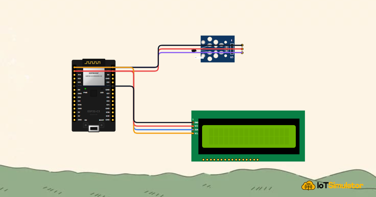
Display Temperature on an LCD with ESP32
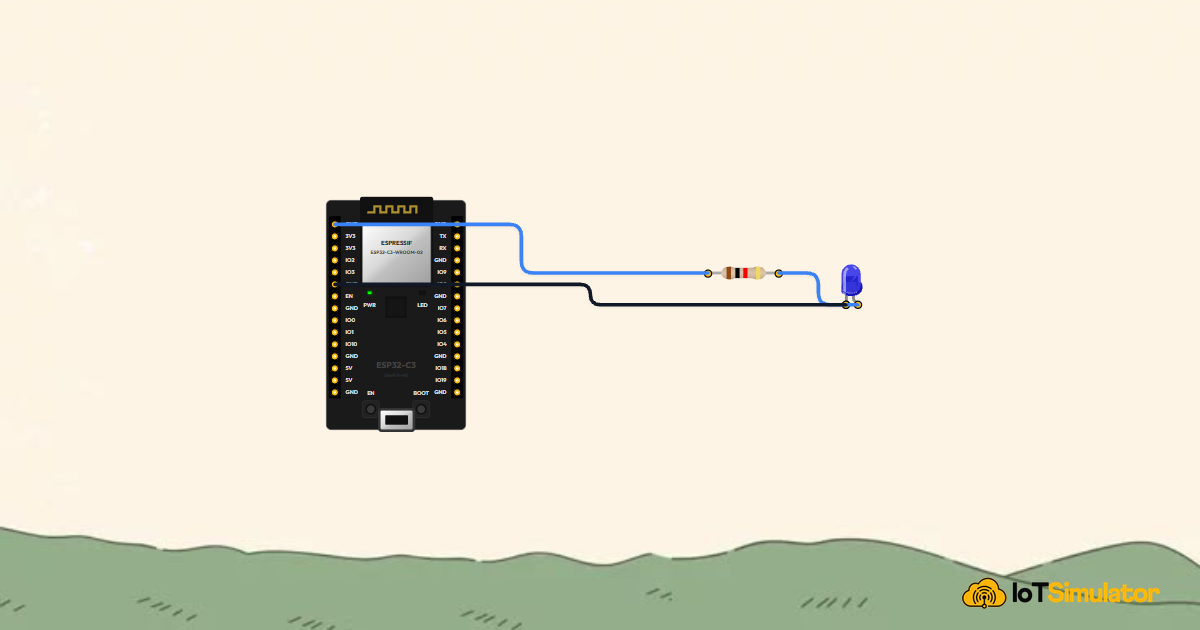
Blink an LED with an ESP32
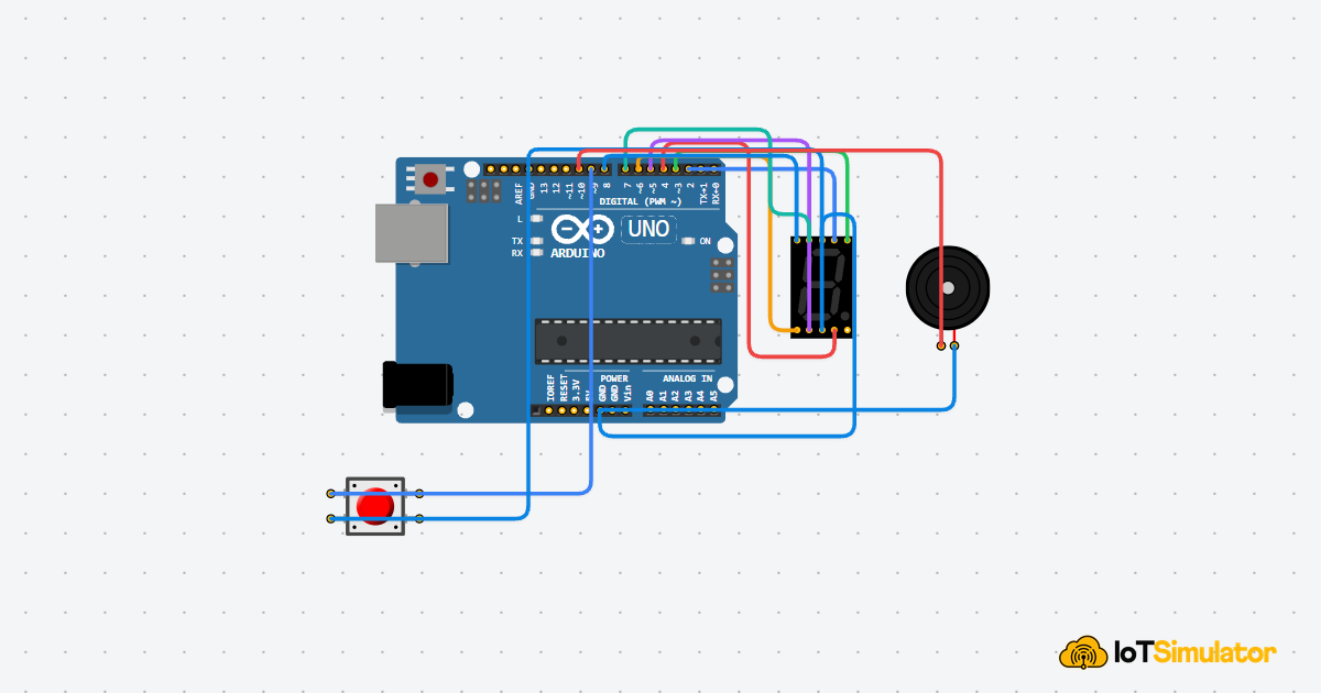
Build a 7-Segment Countdown with Arduino
Build a Mini Stopwatch Using Arduino
Display Heartbeat BPM on an Arduino LCD