When you start learning electronics with microcontrollers, traditional 8-bit boards like the Arduino Uno provide a wonderful starting point. But as your projects grow—whether you are synthesizing retro synthesizer chiptunes, calculating inverse kinematics for robotic arms, or driving color TFT graphics displays—an 8-bit chip running at 16 MHz with 2 KB of memory can quickly run out of speed and room.
The Raspberry Pi Pico changes the game. Designed by the Raspberry Pi Foundation around their own custom-built RP2040 silicon chip, the Pico brings high-speed 32-bit dual-core processing, generous memory, high-resolution analog inputs, and revolutionary Programmable I/O (PIO) to a board that costs less than a cup of coffee.
This comprehensive guide introduces the Raspberry Pi Pico from the ground up: what the board does, how its dual cores work, what you need to know about 3.3V logic levels, how to wire simple circuits, and how to write multi-threaded code using the familiar Arduino IDE syntax.
Description
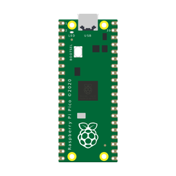
The Raspberry Pi Pico is a compact, breadboard-friendly microcontroller development board. Unlike single-board computers like the Raspberry Pi 4 or 5 that run full Linux operating systems with desktop monitors and keyboards, the Pico is a pure microcontroller. It runs your compiled code directly on bare metal without boot delays or operating system overhead.
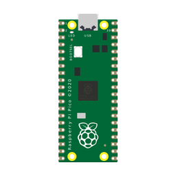
At the center of the board sits the RP2040 chip, containing two 32-bit ARM Cortex-M0+ cores clocked at a speedy 125 MHz (and easily overclockable to 250 MHz+). Surrounding the chip are 264 KB of internal multi-bank SRAM and 2 MB of high-speed external QSPI flash memory.
A standout feature of the Pico is its unique physical pin design: the 40 outer pins have both standard through-hole pin header holes for breadboard prototyping and castellated solder edges, allowing you to solder the entire board flat onto a custom motherboard like an SMD module.
Key Technical Specifications
Here is a complete breakdown of the Raspberry Pi Pico's hardware specifications and what each feature means for your electronics builds:
| Hardware Feature | Technical Specification | What It Means in Plain English |
|---|---|---|
| Processor Core | Dual-Core ARM Cortex-M0+ @ 125 MHz (32-bit) | Two independent 32-bit computer brains running side-by-side at roughly 8x the clock speed of an Arduino Uno. |
| SRAM Working Memory | 264 KB on-chip SRAM | Massive working memory for large graphics display buffers, audio waveforms, and complex sensor arrays. |
| Program Flash Storage | 2 MB (2,048 KB) QSPI Flash | Holds huge programs, custom fonts, audio samples, and file systems with space to spare. |
| General Purpose I/O (GPIO) | 26 Multi-Function Pins (3.3V Logic) | Dozens of pins to connect sensors, switches, motors, displays, and communication buses. |
| Analog-to-Digital Converter | 3 External Channels (12-bit: 0 – 4095) | 4x finer sensitivity than 10-bit Arduino inputs for precision voltage and sensor measurements. |
| Hardware Timers & PWM | 16 Channels across 8 PWM Slices | Independent hardware pulse generation for LED dimming, servos, and buzzer frequencies. |
| Serial Interfaces | 2x UART, 2x SPI, 2x I2C | Multiple hardware communication buses to talk to multiple sensors and displays simultaneously. |
| Programmable I/O (PIO) | 8 State Machines (2 Blocks) | Custom hardware coprocessors that can emulate custom protocols (like DVI video or WS2812 LED timing) with cycle-accurate precision without taxing the main CPU. |
| Operating Voltage | 1.8V to 5.5V input (Internal 3.3V Regulator) | Can be powered from 5V USB, 3x AA batteries, LiPo battery cells, or bench power supplies. |
Raspberry Pi Pico vs Other Microcontroller Boards
To understand where the Pico fits into your maker toolkit, here is a direct comparison against other popular microcontroller boards:
| Comparison Metric | Raspberry Pi Pico | Arduino Uno R3 | ESP32-C3 DevKit | Raspberry Pi 5 (SBC) |
|---|---|---|---|---|
| Board Type | Microcontroller (No OS) | Microcontroller (No OS) | Microcontroller (No OS) | Single-Board Computer (Linux OS) |
| Processor Core | Dual-Core 32-bit ARM @ 125 MHz | Single-Core 8-bit AVR @ 16 MHz | Single-Core 32-bit RISC-V @ 160 MHz | Quad-Core 64-bit ARM @ 2.4 GHz |
| RAM Memory | 264 KB | 2 KB | 400 KB | 4 GB – 8 GB |
| Flash Storage | 2 MB | 32 KB | 4 MB | MicroSD / NVMe SSD |
| Logic Voltage | 3.3V Logic Only | 5.0V Logic | 3.3V Logic Only | 3.3V Logic Only |
| Wireless Networking | None (Pico W adds Wi-Fi) | None (USB only) | Built-in Wi-Fi & BLE 5.0 | Gigabit Ethernet & Dual-Band Wi-Fi |
| Starting Price | Extremely Low (~$4) | Moderate (~$20–$25) | Low (~$5) | High (~$60–$80) |
| Best Project Role | Fast robotics, audio synthesis, motor control, math | Classroom beginner circuits & 5V legacy modules | Wireless IoT sensors, web dashboards, MQTT | Machine learning, computer vision, servers, UI |
Pinout & Pin Basics
The Raspberry Pi Pico features 40 physical pin pads arranged in two neat 20-pin columns. Looking at the board with the micro-USB connector pointing UP, the pins are numbered 1 to 20 on the left side (top to bottom) and 21 to 40 on the right side (bottom to top).
| Pin # | Pin Label | Primary Functions & Special Hardware Capabilities |
|---|---|---|
| Pins 1, 2 | GP0, GP1 | Digital GPIO, UART0 (TX/RX), I2C0 (SDA/SCL), PWM 0A/0B. |
| Pin 3 | GND | Common Ground Reference. |
| Pins 4, 5 | GP2, GP3 | Digital GPIO, I2C1 (SDA/SCL), SPI0 (SCK/TX), PWM 1A/1B. |
| Pins 6, 7 | GP4, GP5 | Digital GPIO, UART1 (TX/RX), I2C0 (SDA/SCL), PWM 2A/2B. |
| Pin 8 | GND | Common Ground Reference. |
| Pins 9–12 | GP6–GP9 | Digital GPIO, SPI0 bus, PWM 3A–4B. |
| Pin 13 | GND | Common Ground Reference. |
| Pins 14–17 | GP10–GP13 | Digital GPIO, SPI1 bus, I2C1 bus, PWM 5A–6B. |
| Pin 18 | GND | Common Ground Reference. |
| Pins 19, 20 | GP14, GP15 | Digital GPIO, UART0 bus, PWM 7A/7B. |
| Pins 21, 22 | GP16, GP17 | Digital GPIO, SPI0 bus, UART0 bus, PWM 0A/0B. |
| Pin 23 | GND | Common Ground Reference. |
| Pins 24–27 | GP18–GP21 | Digital GPIO, SPI0 bus, I2C0 bus, PWM 1A–2B. |
| Pin 28 | GND | Common Ground Reference. |
| Pin 29 | GP22 | Digital GPIO, PWM 3A. |
| Pin 30 | RUN | Hardware Reset Pin. Pull to GND to restart the processor. |
| Pin 31 | GP26 / ADC0 | Analog Input 0 (A0) or Digital GPIO 26, PWM 5A. |
| Pin 32 | GP27 / ADC1 | Analog Input 1 (A1) or Digital GPIO 27, PWM 5B. |
| Pin 33 | GND | Analog Ground Reference. |
| Pin 34 | GP28 / ADC2 | Analog Input 2 (A2) or Digital GPIO 28, PWM 6A. |
| Pin 35 | ADC_VREF | Analog Voltage Reference input (defaults to clean 3.3V). |
| Pin 36 | 3V3 | Clean 3.3V Regulated Power Output (up to 300 mA for sensors). |
| Pin 37 | 3V3_EN | Enable line for onboard 3.3V regulator (pull LOW to power down). |
| Pin 38 | GND | Common Ground Reference. |
| Pin 39 | VSYS | Main system power input (1.8V to 5.5V battery or external supply). |
| Pin 40 | VBUS | 5.0V Raw Power directly from Micro-USB cable. |
| Onboard | GP25 | Connected directly to the green onboard status LED. |
Crucial Safety Rule: Strict 3.3V Logic Levels
The most important beginner rule to remember with the Raspberry Pi Pico is that all GPIO pins operate at 3.3V logic. Unlike traditional Arduino Uno boards whose pins can safely accept 5.0V signals, the RP2040 silicon pins are NOT 5V tolerant. Connecting a 5V sensor signal directly to a Pico GPIO pin will permanently fry the internal transistors. When working with 5V sensor outputs, always use a bidirectional logic level shifter or a simple two-resistor voltage divider.
High-Resolution 12-Bit Analog Converters
The Pico features three external 12-bit analog input channels: GP26 (A0), GP27 (A1), and GP28 (A2). While an Arduino Uno only reads values from 0 to 1023 (10-bit), the Pico reads from 0 to 4095 (12-bit). That means you get 4,096 distinct voltage steps, allowing you to detect tiny changes in light, temperature, or potentiometer position with exceptional precision.
How to Power the Raspberry Pi Pico
The Pico has an intelligent built-in buck-boost power circuit (RT6150) that makes power management remarkably flexible:
- Micro-USB Power: Plugging the micro-USB cable into your computer provides 5V to the board. Pin 40 (
VBUS) outputs this raw 5V supply, which is perfect for powering high-current 5V servo motors or relay coils without loading the processor. - VSYS Battery Input (Pin 39): You can connect any battery pack providing between 1.8V and 5.5V (such as 3x AA batteries, a 3.7V LiPo cell, or a 5V power bank) directly to Pin 39 (
VSYS). The onboard power chip automatically regulates it down to a rock-solid 3.3V for the CPU. - 3V3 Power Output (Pin 36): This pin delivers clean, regulated 3.3V power (up to ~300 mA) to feed external breakout boards, OLED displays, and analog sensors.
Common Components Used With Raspberry Pi Pico
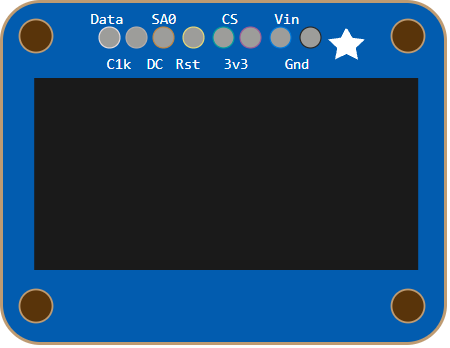
Because the Pico has 26 GPIO pins and high processing speed, it pairs effortlessly with modern 3.3V electronics:
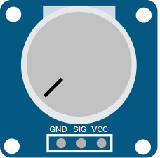
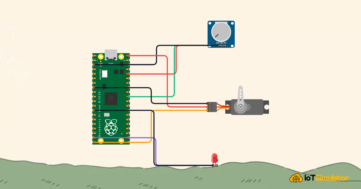
Interactive Circuit Demo: Potentiometer Dial & Servo Actuator
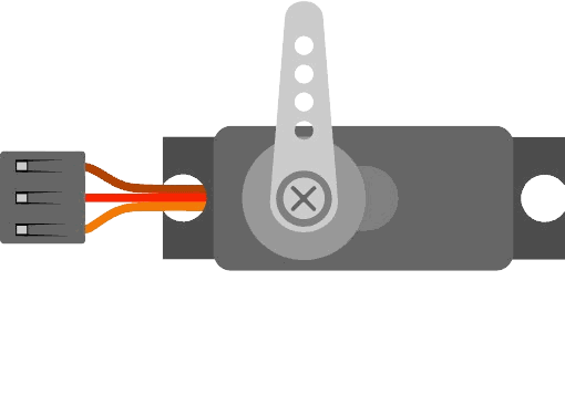
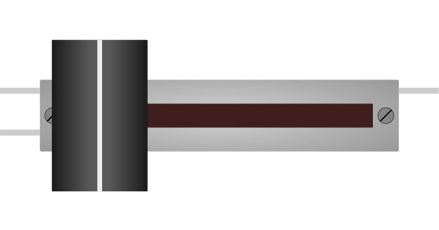
Below is an interactive circuit simulation. The Raspberry Pi Pico reads an analog control knob on pin GP26 (ADC0) and commands an SG90 servomotor on pin GP15 using high-precision hardware PWM pulses:

Pin Connection Table
Complete Starter Sketch
Upload the following Arduino sketch to your Raspberry Pi Pico to control the servo angle from the potentiometer dial:
// ============================================================================
// Raspberry Pi Pico Precision Servo Angle Controller
// Potentiometer Analog Input on GP26 (ADC0) | Servo PWM Output on GP15
// ============================================================================

#include <Servo.h>

Servo myServo;
const int POT_PIN   = 26; // Analog ADC0 (Physical Pin 31)
const int SERVO_PIN = 15; // PWM Servo Signal (Physical Pin 20)

void setup() {
  Serial.begin(115200);
  delay(200); // Allow USB serial to stabilize

  // Configure 12-bit ADC reading (0 to 4095)
  analogReadResolution(12);

  // Attach the servo motor to hardware PWM pin GP15
  myServo.attach(SERVO_PIN);

  Serial.println(F("Raspberry Pi Pico Servo Controller Ready!"));
}

void loop() {
  // 1. Read 12-bit analog dial position (0 to 4095)
  int rawPot = analogRead(POT_PIN);

  // 2. Map 12-bit range to 0-180 angular degrees
  int angle = map(rawPot, 0, 4095, 0, 180);
  angle = constrain(angle, 0, 180);

  // 3. Command the servo to move to the target angle
  myServo.write(angle);

  // 4. Print debug telemetry to Serial Monitor
  Serial.print(F("ADC: "));
  Serial.print(rawPot);
  Serial.print(F(" -> Target Angle: "));
  Serial.print(angle);
  Serial.println(F("°"));

  delay(20); // 50 Hz smooth update cycle
}
How the Code Works, Part by Part
Let's break down the key parts of the Raspberry Pi Pico sketch:
1. Configuring 12-bit Analog Precision
In the setup() function, we call analogReadResolution(12):
analogReadResolution(12);
myServo.attach(SERVO_PIN);
By default, Arduino IDE compatibility layers scale analog readings down to 10 bits (0–1023). Enabling native 12-bit mode unlocks the full 4096-step precision of the RP2040 hardware converter.
2. True Dual-Core Multi-Threading (Optional Power Feature)
In standard Arduino AVR boards, code is restricted to a single setup() and loop(). But with the Raspberry Pi Pico Arduino core, you can declare a second execution thread by simply creating setup1() and loop1():
void setup1() {
  // Core 1 initialization
}

void loop1() {
  // Core 1 runs continuously in parallel with Core 0!
}
Core 0 and Core 1 run independently at 125 MHz. You can dedicate Core 0 to real-time motor control and sensor polling while Core 1 computes mathematical filters or refreshes an OLED screen, eliminating stutter and lag completely.
Fixing Common Problems
If you encounter issues when working with the Raspberry Pi Pico, consult this troubleshooting guide:
| Observed Symptom | Likely Cause | How to Fix It |
|---|---|---|
| Pico does not appear as a COM port in Arduino IDE | Board is in USB mass-storage bootloader mode or needs a fresh UF2 upload | Hold down the white BOOTSEL button while plugging in the USB cable. The Pico will mount as a drive named RPI-RP2. Select the Raspberry Pi Pico board in Arduino IDE and click Upload. |
| Analog readings jump around randomly or do not reach 3.3V | Potentiometer wired to 5V instead of 3.3V, or floating pin | Ensure the potentiometer outer leg is connected to Pin 36 (3V3) and not Pin 40 (VBUS). Confirm ADC ground connects to Pin 33 (AGND). |
| Servo motor jitters or board restarts when motor turns | Motor power drawn from 3.3V logic regulator causing voltage brownouts | Move the servo red wire to Pin 40 (VBUS), which draws power directly from the 5V USB line without passing through the sensitive 3.3V CPU regulator. |
| Serial Monitor shows no output | Baud rate mismatch or missing USB initialization delay | Ensure Serial.begin(115200) matches the Serial Monitor baud rate setting, and add a delay(200) in setup to let the USB connection enumerate. |
Wrapping Up
The Raspberry Pi Pico brings 32-bit dual-core computing power, massive memory, high-resolution analog inputs, and revolutionary PIO coprocessors into an ultra-affordable, beginner-friendly package.
Whether you are building robotic controllers, audio synthesizers, or high-speed sensor instruments, the Pico provides endless headroom to grow your maker skills.