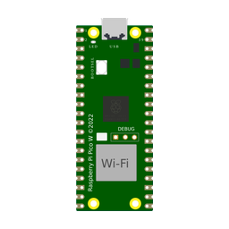
Imagine taking all the raw computing speed, dual-core architecture, and generous memory of the Raspberry Pi Pico—and adding a built-in wireless radio so it can connect to your home Wi-Fi network, host its own web pages, and stream sensor telemetry straight to your smartphone. That is exactly what the Raspberry Pi Pico W delivers.
By pairing the custom RP2040 dual-core processor with an onboard Infineon CYW43439 wireless chip, the Pico W enables makers to build connected smart-home gadgets, cloud weather stations, remote motor controllers, and wireless IoT nodes for just a couple dollars more than the original Pico.
This complete beginner's guide explains how the Pico W works, how its wireless chip interacts with the CPU, what you need to know about its 3.3V logic and onboard LED differences, and how to write your very first Wi-Fi web server sketch.
Description
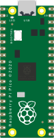
The Raspberry Pi Pico W is the wireless-enabled version of the popular Raspberry Pi Pico. It retains the identical physical dimensions, 40-pin layout, and pinout compatibility of the original board, making it a drop-in replacement for existing Pico projects that need wireless capabilities.
The most visible upgrade on the Pico W is the silver metal RF shield can near the micro-USB port. Inside that metal enclosure sits an Infineon CYW43439 wireless modem supporting single-band 2.4 GHz 802.11b/g/n Wi-Fi and Bluetooth 5.2 (including Bluetooth Low Energy). At the top edge of the board, an onboard 2.4 GHz PCB antenna eliminates the need for bulky external antenna cables.
In real-world projects, the Pico W is used in Wi-Fi climate monitors, smart home relays that integrate with Home Assistant, wireless plant monitors, remote environmental data loggers, and automated NTP network clocks that synchronize with global time servers automatically.
Key Technical Specifications
Here is what makes the Raspberry Pi Pico W such a powerhouse for wireless IoT development:
| Feature | Technical Specification | What It Means in Plain English |
|---|---|---|
| Processor Core | RP2040 Dual-Core ARM Cortex-M0+ @ 125 MHz | Dual 32-bit cores provide plenty of power to manage wireless networking on one core while running real-time hardware tasks on the other. |
| Wireless Modem | Infineon CYW43439 (2.4 GHz) | Provides reliable 802.11b/g/n Wi-Fi connection (softAP, station, client) and Bluetooth 5.2 / BLE support. |
| Onboard Antenna | ABRACON 2.4 GHz Resonant Cavity Antenna | Built directly into the circuit board for clean reception without extra wires or external antennas. |
| Memory | 264 KB SRAM + 2 MB QSPI Flash | Abundant memory to store HTML web pages, JSON payloads, SSL certificates, and network buffers. |
| GPIO Pins | 26 Multi-function 3.3V Pins | Fully backwards-compatible pinout with the original Pico for easy breadboard prototyping. |
| Analog Inputs (ADC) | 3 Channels (12-bit: 0 – 4095) | High-resolution analog measurement for light sensors, moisture sensors, and battery voltage monitoring. |
| Logic Level | Strict 3.3V Logic Levels | Signals must stay between 0V and 3.3V (do not connect 5V sensors directly). |
| Power Supply | 1.8V to 5.5V (Micro-USB / VSYS) | Can run directly on USB 5V, 3.7V LiPo rechargeable batteries, or 3x AA battery packs. |
Raspberry Pi Pico W vs Original Pico vs ESP32
How does the Pico W compare against the standard Pico and other popular wireless IoT boards like the ESP32? Review the table below:
| Comparison Feature | Raspberry Pi Pico W | Standard Pico (Non-Wireless) | ESP32-C3 DevKit |
|---|---|---|---|
| Wi-Fi Networking | Built-in 2.4 GHz 802.11n Wi-Fi | No wireless connectivity | Built-in 2.4 GHz Wi-Fi |
| Bluetooth Support | Bluetooth 5.2 / BLE | No Bluetooth | Bluetooth 5.0 LE |
| Processor Core | Dual-Core ARM Cortex-M0+ @ 125 MHz | Dual-Core ARM Cortex-M0+ @ 125 MHz | Single-Core RISC-V @ 160 MHz |
| Programmable I/O (PIO) | 8 State Machines (PIO) | 8 State Machines (PIO) | No PIO (standard peripherals) |
| SRAM Memory | 264 KB multi-bank RAM | 264 KB multi-bank RAM | 400 KB RAM |
| Onboard Status LED | Connected through wireless chip (LED_BUILTIN) | Connected to GPIO 25 | Connected to GPIO 8 (RGB LED) |
| Best Project Fit | Connected smart home gadgets, IoT web servers | Offline robotics, sound synthesis, fast math | Battery IoT sensors, low-power sleep beacons |
Pinout & Crucial Hardware Differences
The physical 40-pin layout of the Pico W matches the standard Pico pin-for-pin. You get the same 26 multi-function GPIO pins, three 12-bit ADC channels (GP26, GP27, GP28), hardware PWM slices, and communication headers (2x I2C, 2x SPI, 2x UART).
The Big Onboard LED Difference
On the standard non-wireless Pico, the green status LED is hardwired to GP25. On the Pico W, however, pin GP25 was reassigned to communicate with the Infineon wireless chip! The green onboard LED on the Pico W is connected directly to a GPIO pin on the wireless chip itself.
In your Arduino sketches, always use the universal constant LED_BUILTIN instead of raw pin number 25. The Arduino-Pico core automatically routes commands to the wireless chip to toggle the LED safely.
3.3V Logic Level Rules
Just like the original Pico, all GPIO pins on the Pico W operate strictly at 3.3V logic. Never feed 5.0V directly from old Arduino sensors into the Pico W pins. Use a logic level shifter or resistor divider when interfacing with 5V components.
How to Power the Pico W
Wireless transmission causes brief current spikes when the radio broadcasts packets. The Pico W's power supply circuit handles this seamlessly:
- Micro-USB (Pin 40 VBUS): Delivers 5V power from your computer or phone charger. Pin 40 outputs the raw 5V supply to power external 5V modules.
- Battery Power (Pin 39 VSYS): Connect any power source from 1.8V to 5.5V (such as a 3.7V LiPo battery or battery holder) to Pin 39 (
VSYS). The onboard power regulator converts it cleanly into 3.3V. - Power Output (Pin 36 3V3): Provides up to 300 mA of regulated 3.3V power for external sensors, OLED screens, and modules.
Common Components Used With Pico W
The Pico W is the ideal heart for modern connected IoT projects:
Interactive Circuit Demo: Smart Climate Dashboard with OLED
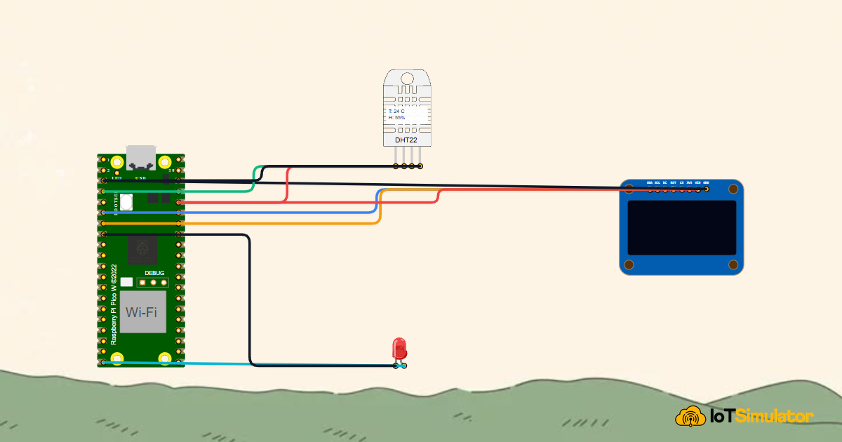
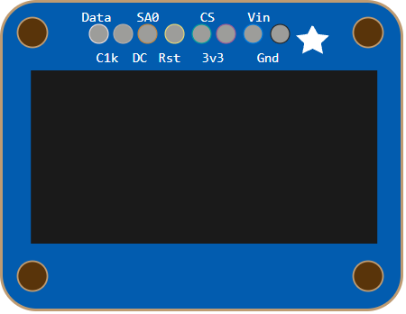
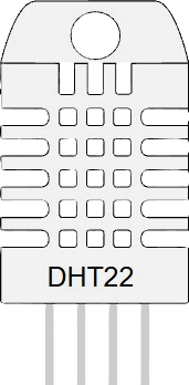
Below is an interactive circuit simulation. The Pico W reads a DHT22 temperature and humidity sensor on GP15 and displays live sensor telemetry on an SSD1306 I2C OLED display connected to I2C0 (GP4 SDA / GP5 SCL):

Pin Connection Table
Complete Starter Sketch: Web Server Control
Upload this sketch to turn your Pico W into a standalone Wi-Fi web server. Open your browser on any phone or laptop connected to the same Wi-Fi network and navigate to the Pico W's IP address:
// ============================================================================
// Raspberry Pi Pico W - Standalone Wi-Fi Web Server & Live Status LED
// Connects to local Wi-Fi and serves an interactive web page to control an LED
// ============================================================================

#include <WiFi.h>

const char* ssid     = "YOUR_WIFI_NAME";
const char* password = "YOUR_WIFI_PASSWORD";

WiFiServer server(80);
const int EXTERNAL_LED = 15; // External LED on GP15

void setup() {
  Serial.begin(115200);
  pinMode(LED_BUILTIN, OUTPUT); // Onboard Wi-Fi LED
  pinMode(EXTERNAL_LED, OUTPUT);

  delay(2000); // Allow USB serial to connect
  Serial.print(F("Connecting to Wi-Fi: "));
  Serial.println(ssid);

  WiFi.begin(ssid, password);
  while (WiFi.status() != WL_CONNECTED) {
    delay(500);
    Serial.print(F("."));
  }

  Serial.println(F(""));
  Serial.println(F("WiFi connected successfully!"));
  Serial.print(F("Pico W Web Server IP Address: "));
  Serial.println(WiFi.localIP());

  server.begin();
  digitalWrite(LED_BUILTIN, HIGH); // Solid ON when connected
}

void loop() {
  WiFiClient client = server.available();
  if (!client) return;

  String request = client.readStringUntil('\r');
  client.flush();

  if (request.indexOf("/LED=ON") != -1)  digitalWrite(EXTERNAL_LED, HIGH);
  if (request.indexOf("/LED=OFF") != -1) digitalWrite(EXTERNAL_LED, LOW);

  // Send HTTP Response
  client.println(F("HTTP/1.1 200 OK"));
  client.println(F("Content-Type: text/html"));
  client.println(F("Connection: close"));
  client.println();
  client.println(F("<!DOCTYPE HTML><html><head><title>Pico W Control</title></head>"));
  client.println(F("<body style='font-family:sans-serif; text-align:center; padding:40px;'>"));
  client.println(F("<h1>Raspberry Pi Pico W Web Server</h1>"));
  client.println(F("<p><a href='/LED=ON'><button style='padding:12px 24px; font-size:16px; background:#22c55e; color:white; border:none; border-radius:8px;'>Turn LED ON</button></a></p>"));
  client.println(F("<p><a href='/LED=OFF'><button style='padding:12px 24px; font-size:16px; background:#ef4444; color:white; border:none; border-radius:8px;'>Turn LED OFF</button></a></p>"));
  client.println(F("</body></html>"));

  delay(1);
}
How the Code Works, Part by Part
Let's look at the key steps in running a web server on the Pico W:
1. Connecting to Wi-Fi
In setup(), we call WiFi.begin(ssid, password):
WiFi.begin(ssid, password);
while (WiFi.status() != WL_CONNECTED) {
  delay(500);
}
Serial.println(WiFi.localIP());
The RP2040 commands the Infineon CYW43439 chip over internal SPI lines to negotiate WPA2 authentication with your wireless router and obtain a local IP address via DHCP.
2. Serving Web Requests and Controlling GPIO
In loop(), the server listens on Port 80 for incoming web browser connections:
if (request.indexOf("/LED=ON") != -1)  digitalWrite(EXTERNAL_LED, HIGH);
if (request.indexOf("/LED=OFF") != -1) digitalWrite(EXTERNAL_LED, LOW);
When you click the button in your web browser, the browser sends an HTTP GET request containing /LED=ON. The Pico W parses this string and immediately toggles digital pin GP15 to switch the light.
Fixing Common Problems
If your Pico W wireless project is not connecting or behaving strangely, review this troubleshooting guide:
| Observed Symptom | Likely Cause | How to Fix It |
|---|---|---|
| Pico W continuously prints dots (....) and will not connect to Wi-Fi | Network is 5.0 GHz only or credentials are misspelled | The Pico W only supports 2.4 GHz Wi-Fi networks. Ensure your router has 2.4 GHz enabled (802.11b/g/n) and verify SSID and password spelling. |
digitalWrite(25, HIGH) does not turn on the onboard LED | Using pin 25 on Pico W instead of the wireless chip constant | Change your code to use digitalWrite(LED_BUILTIN, HIGH). On Pico W, the onboard LED is routed through the CYW43439 modem. |
| Web server loads very slowly or drops packets | Weak signal or board placed on metal surface blocking the PCB antenna | Ensure the top edge containing the triangular PCB antenna is not covered by metal shields or placed on conducting surfaces. |
Compilation error: WiFi.h: No such file or directory | Wrong board selected in Arduino IDE | In the Arduino IDE Boards menu, select Raspberry Pi Pico W (from the Raspberry Pi Pico/RP2040 package by Earle Philhower) instead of the standard non-wireless Pico. |
Wrapping Up
The Raspberry Pi Pico W opens up the world of connected IoT at an unbeatable price point. With dual-core processing, hardware PIO state machines, and high-speed 2.4 GHz Wi-Fi and Bluetooth, it is the ultimate board for modern smart home automation, remote monitoring, and IoT innovation.