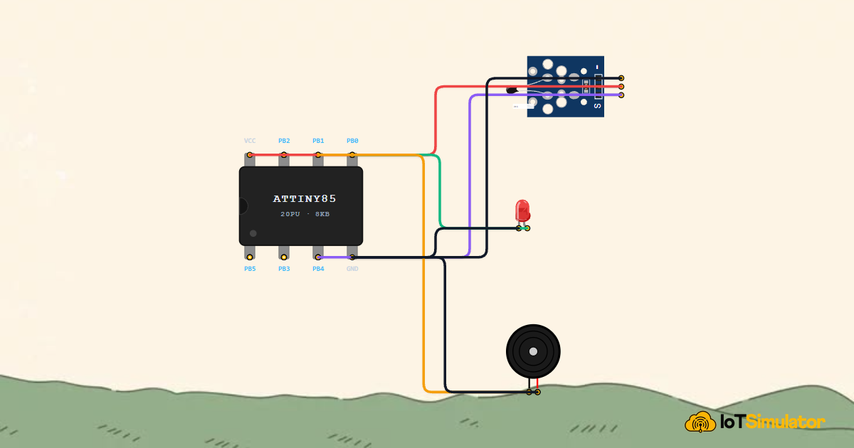
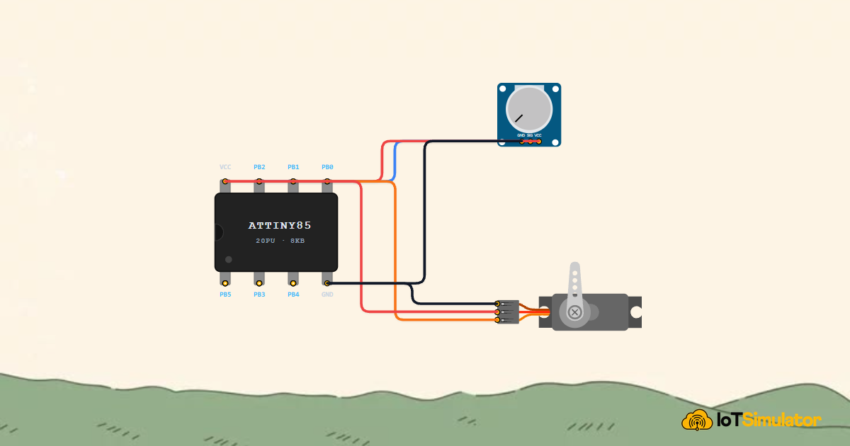
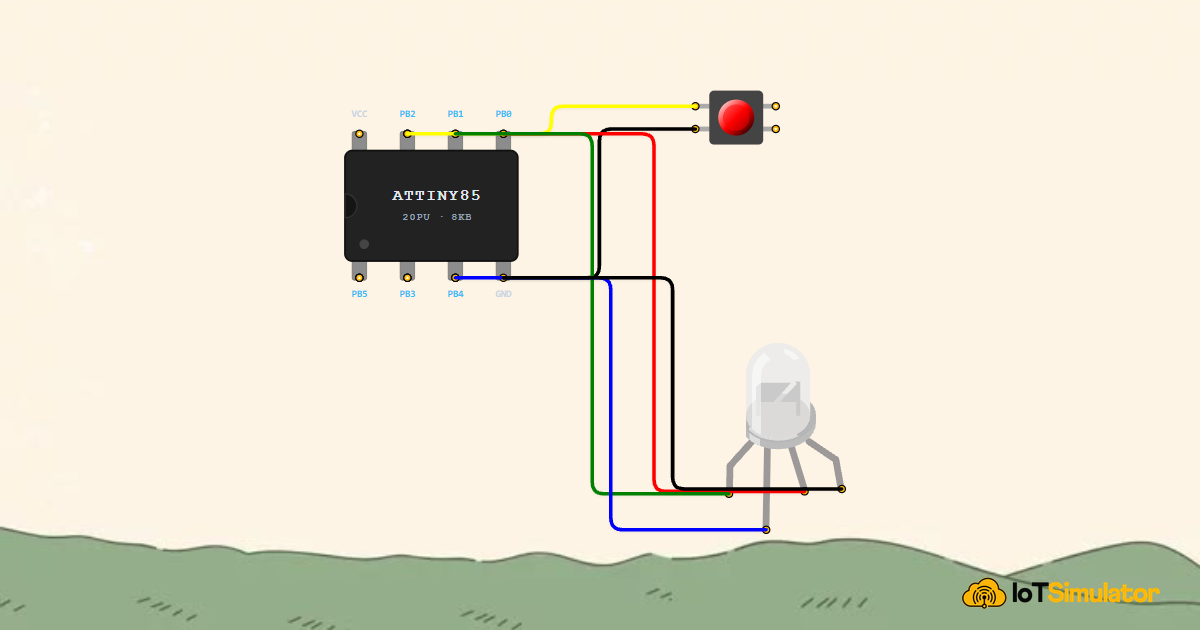
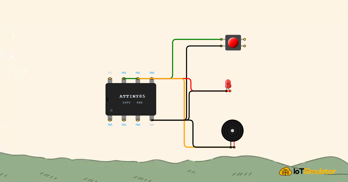
When you want to build a tiny smart gadget—like a glowing ring, a battery-powered bike flasher, an automatic plant soil buzzer, or a pocket game timer—an entire Arduino Uno development board is far too large and power-hungry. You do not need dozens of pins or a bulky USB cable taking up space in your enclosure. What you really need is a tiny, powerful computer chip that fits on the tip of your finger.
That is where the ATtiny85 comes in. Inside an 8-pin dual in-line package (DIP-8) that measures less than one square centimeter, the ATtiny85 gives you an authentic AVR processor that runs real Arduino C++ code, controls LEDs, reads analog sensors, and runs for months on a single watch battery.
This complete beginner's guide explains what the ATtiny85 does, how its pins work, how it compares to larger boards, how to wire simple circuits, and how to write clean code for your own miniature electronics projects.
Description
The ATtiny85 is a compact 8-bit microcontroller manufactured by Microchip (originally Atmel). Unlike a complete development board that includes voltage regulators, USB chips, and rows of female headers, the ATtiny85 is a bare integrated circuit (IC). You place it directly into a breadboard or solder it onto a miniature circuit board.
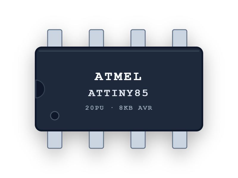
Despite its pocket size, the ATtiny85 contains everything needed to execute programs: a central processing unit (CPU), built-in program memory (Flash), working memory for live variables (SRAM), persistent storage (EEPROM), internal clock oscillators, precision timers, and analog-to-digital converters.
In real-world projects, makers love the ATtiny85 for wearable electronic jewelry, flashlight controllers, holiday ornaments, interactive toys, auto-shutoff safety switches, and low-cost sensor nodes where every millimeter and milliamp counts.
Key Technical Specifications
Here is what you need to know about the technical capabilities of the ATtiny85 and what each specification means for your project:
| Specification | Technical Value | What It Means in Plain English |
|---|---|---|
| Microcontroller Core | 8-bit AVR RISC | The central brain that executes your code instructions step by step. |
| Program Flash Memory | 8 KB (8,192 Bytes) | Your program's long-term bookshelf. Holds roughly 2,000 to 4,000 lines of Arduino machine code. |
| RAM (SRAM) | 512 Bytes | Live scratchpad memory for temporary variables, loop counters, and function calls. |
| EEPROM Storage | 512 Bytes | Non-volatile memory that remembers user settings or high scores even when power is disconnected. |
| Clock Speed | 1 MHz, 8 MHz, or 16 MHz (Internal PLL) | How fast the chip thinks. Runs fast enough for animations, sensor readings, and servo pulses without needing an external crystal. |
| Operating Voltage | 2.7V – 5.5V (Standard) / 1.8V – 5.5V (ATtiny85V) | Runs comfortably on 5V USB power, 3.3V supplies, 2x AAA batteries, or a 3V CR2032 coin cell. |
| Programmable I/O Pins | 6 General Purpose I/O Pins (PB0 to PB5) | 6 pins to connect buttons, LEDs, buzzers, sensors, and displays. |
| Hardware Timers & PWM | 2x 8-Bit Timers (Timer0 & Timer1) | Built-in pulse generation for dimming LEDs, creating speaker tones, and driving RC servo motors. |
| Analog Inputs (ADC) | 4 Channels (10-bit resolution: 0 – 1023) | Measures gradual voltage changes from potentiometers, light sensors (LDR), and thermistors. |
| Serial Interfaces | Universal Serial Interface (USI) | Software-compatible with I2C (OLED screens, RTC clocks) and SPI communication. |
ATtiny85 vs Other Microcontroller Boards
Choosing the right microcontroller board is all about matching the hardware to your project's physical space, power budget, and complexity. Here is how the ATtiny85 compares to other popular boards in the maker ecosystem:
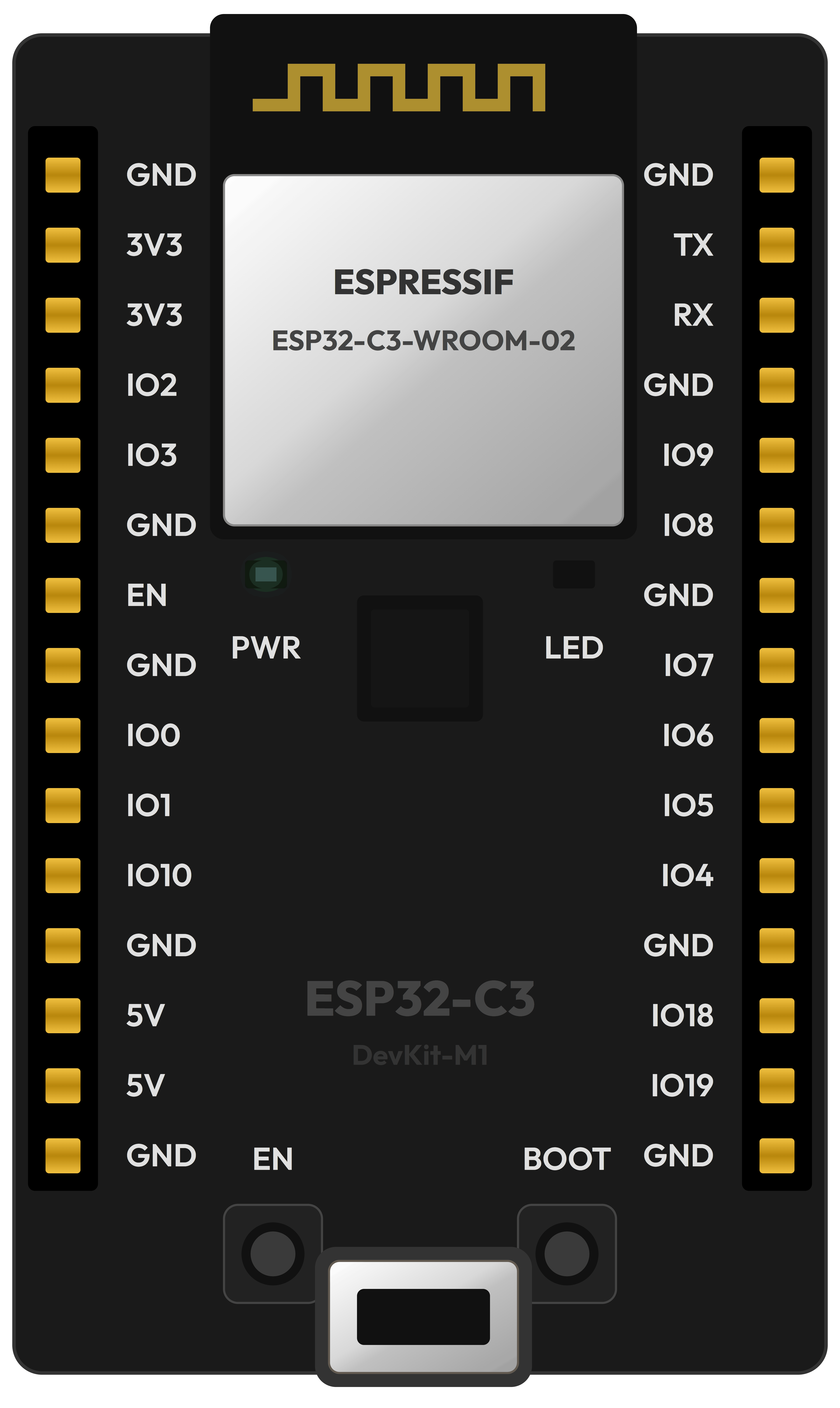
| Comparison Factor | ATtiny85 | Arduino Uno | Raspberry Pi Pico | ESP32-C3 DevKit |
|---|---|---|---|---|
| Physical Size | Ultra-tiny (DIP-8 chip: 9 x 7 mm) | Large (68 x 53 mm) | Medium breadboard stick (51 x 21 mm) | Compact IoT stick (48 x 25 mm) |
| Usable GPIO Pins | 6 Pins | 14 Digital + 6 Analog (20 total) | 26 Multi-function Pins | 15 Multi-function Pins |
| Processor & Speed | 8-bit AVR @ 8 / 16 MHz | 8-bit AVR @ 16 MHz | 32-bit Dual-Core ARM @ 125 MHz | 32-bit RISC-V @ 160 MHz |
| Flash / SRAM Memory | 8 KB Flash / 512 B RAM | 32 KB Flash / 2 KB RAM | 2 MB Flash / 264 KB RAM | 4 MB Flash / 400 KB RAM |
| Wireless Connectivity | None (pure standalone hardware) | None (USB only) | None (Pico W adds Wi-Fi/BT) | Built-in 2.4 GHz Wi-Fi + Bluetooth LE |
| Idle Power Consumption | Micro-amps (< 0.005 mA in sleep) | ~45 mA (regulators + USB chip) | ~20 mA | ~15–80 mA |
| Best Project Role | Mini wearables, coin-cell gadgets, flashers | Classroom learning & desktop prototyping | Fast robotics, math, audio & multi-core control | Smart home IoT, Wi-Fi web servers, cloud alerts |
ATtiny85 DIP-8 Pinout & Port Guide
Understanding the ATtiny85 pinout is straightforward once you know how integrated circuit pins are counted. Hold the chip so the semi-circular notch (or small circular indicator dot) is at the top. Pin 1 starts at the top-left and counts down counter-clockwise to Pin 4 at the bottom-left. Pin 5 is at the bottom-right and counts up to Pin 8 at the top-right.
| Physical Pin # | Port Name | Arduino Pin ID | Primary Functions & Alternate Hardware Roles |
|---|---|---|---|
| Pin 1 | PB5 | Pin 5 / A0 | RESET Pin (Active LOW). Also functions as ADC0 and debugWIRE programming pin. |
| Pin 2 | PB3 | Pin 3 / A3 | Analog Input A3, External Clock Input (XTAL1 / CLKI), Pin Change Interrupt (PCINT3). |
| Pin 3 | PB4 | Pin 4 / A2 | Analog Input A2, External Clock Output (XTAL2 / CLKO), Pin Change Interrupt (PCINT4). |
| Pin 4 | GND | GND | Ground Reference (0V). Connects to the negative battery terminal and sensor grounds. |
| Pin 5 | PB0 | Pin 0 | Digital Pin 0, Hardware PWM (Timer0 OC0A), I2C Data (SDA), SPI Data In (MOSI/DI). |
| Pin 6 | PB1 | Pin 1 | Digital Pin 1, Hardware PWM (Timer0 OC0B / Timer1 OC1A), SPI Data Out (MISO/DO). |
| Pin 7 | PB2 | Pin 2 / A1 | Digital Pin 2 / Analog Input A1, I2C Clock (SCL), SPI Clock (SCK). |
| Pin 8 | VCC | VCC | Positive Power Supply (+2.7V to +5.5V). Connects to positive battery rail or 5V/3.3V regulator. |
Digital Outputs & Hardware PWM Dimming
Pins 5 and 6 (PB0 and PB1) are the most frequently used output pins because they feature dedicated hardware PWM (Pulse Width Modulation) driven by Timer0. You can use analogWrite(0, value) or analogWrite(1, value) with values from 0 to 255 to smoothly dim LEDs, adjust motor speeds, or drive piezo speakers without using software delay loops.
Reading Analog Sensors (10-bit ADC)
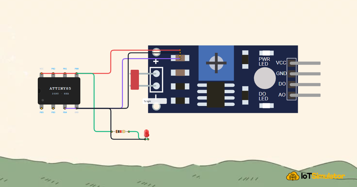
The ATtiny85 has three easily accessible analog input channels: Pin 2 (A3), Pin 3 (A2), and Pin 7 (A1). When you call analogRead(A1), the chip converts incoming sensor voltages into numbers from 0 (0V) up to 1023 (full VCC voltage). This lets you connect light-dependent resistors (LDR), potentiometers, temperature sensors, and moisture probes directly to the chip.
Important Warning: Pin 1 (PB5 / RESET)
Physical Pin 1 defaults to the chip's hardware RESET line. If Pin 1 is pulled down to GND (0V), the microcontroller immediately reboots. In normal breadboard circuits, leave Pin 1 unconnected or connect a 10kΩ pull-up resistor between Pin 1 and VCC. Do NOT use Pin 1 as an ordinary button input unless you are familiar with high-voltage fuse programming, because disabling the Reset fuse makes standard ISP reprogramming impossible.
How to Power the ATtiny85
One of the greatest strengths of the ATtiny85 is its wide operating voltage range and battery efficiency:
- 5V USB Power: Perfect for initial breadboard prototyping. You can power the chip from the 5V rail of an Arduino or USB breakout board.
- 3V CR2032 Lithium Coin Cell: The ultimate power source for pocket-sized wearables. A standard CR2032 coin cell outputs 3.0V, perfectly matching the ATtiny85's 2.7V–5.5V range.
- 2x or 3x AAA / AA Batteries: Two alkaline batteries provide 3.0V, while three provide 4.5V. This provides high capacity for projects that drive high-brightness LEDs or small servo motors for days.
- Low-Power Sleep Modes: By using the AVR
<avr/sleep.h>library, the ATtiny85 can power down into deep sleep when idle, drawing less than 0.005 mA (5 microamps). A single coin cell can power a sleeping sensor for over a year!
Common Components Used With ATtiny85
Because the ATtiny85 has 6 usable pins, it pairs naturally with compact, power-efficient parts:

Interactive Circuit Demo: ATtiny85 LED Pulse & Dimmer
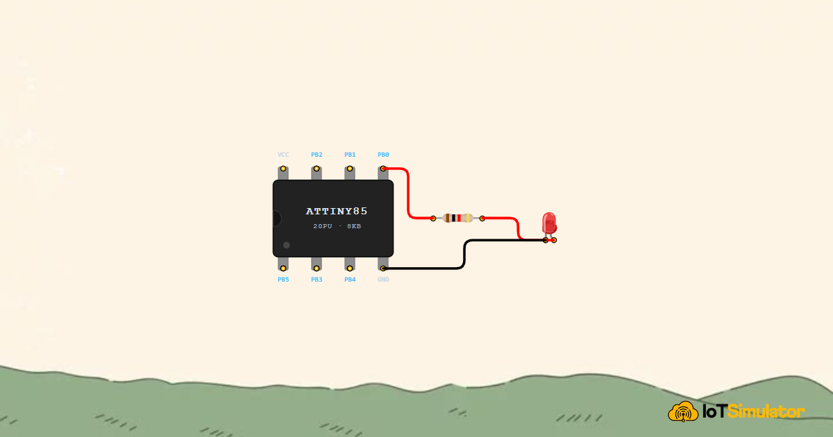
Below is an interactive circuit simulation. The ATtiny85 is wired to a 5mm indicator LED on digital pin PB0 (Physical Pin 5) through a protective 220Ω current-limiting resistor. The ground pin (Pin 4) completes the circuit loop back to the power rail.

Pin Connection Table
Complete Starter Sketch
Upload the sketch below to run a smooth breathing LED animation on your ATtiny85:
// ============================================================================
// ATtiny85 Smooth Breathing LED Animation
// PB0 (Arduino Pin 0) -> 220 Ohm Resistor -> LED -> GND
// ============================================================================

const int ledPin = 0; // PB0 is Arduino Pin 0 (DIP-8 Physical Pin 5)

void setup() {
  // Configure PB0 as a digital output pin
  pinMode(ledPin, OUTPUT);
}

void loop() {
  // 1. Ramp brightness smoothly from OFF (0) to FULL (255)
  for (int brightness = 0; brightness <= 255; brightness += 5) {
    analogWrite(ledPin, brightness);
    delay(15); // Smooth 15ms step delay
  }

  // 2. Ramp brightness smoothly from FULL (255) to OFF (0)
  for (int brightness = 255; brightness >= 0; brightness -= 5) {
    analogWrite(ledPin, brightness);
    delay(15);
  }

  // 3. Brief resting pause at the bottom of the breath
  delay(300);
}
How the Code Works, Part by Part
Let's examine the key building blocks that make this program work:
1. Setup: Declaring the Pin Mode
The setup() function runs once when the chip powers on. We tell the microcontroller to prepare PB0 as an output:
const int ledPin = 0; // PB0 corresponds to Arduino pin 0

void setup() {
  pinMode(ledPin, OUTPUT);
}
In Arduino code for ATtiny85 (via SpenceKonde's ATTinyCore), digital pin numbers match the Port B number: 0 is PB0, 1 is PB1, 2 is PB2, 3 is PB3, and 4 is PB4.
2. Hardware PWM Dimming with analogWrite()
Inside loop(), the for-loop increments the brightness variable from 0 to 255:
for (int brightness = 0; brightness <= 255; brightness += 5) {
  analogWrite(ledPin, brightness);
  delay(15);
}
The analogWrite() function configures the internal 8-bit timer to switch PB0 on and off thousands of times per second. By changing the ratio of ON time to OFF time (the duty cycle), your eyes perceive a smooth, gradual change in light level.
Fixing Common Problems
If your ATtiny85 circuit or code does not behave as expected, check this troubleshooting checklist:
| Observed Symptom | Likely Cause | How to Fix It |
|---|---|---|
| LED stays completely dark | LED polarity reversed or wrong pin number in code | Confirm the longer LED leg (anode) connects to the resistor from PB0 (Pin 5) and the flat edge (cathode) connects to GND. Verify code uses pinMode(0, OUTPUT). |
| Timers and delays run 8x too slow (e.g. 1 second delay takes 8 seconds) | Factory clock fuse mismatch (chip is running at 1 MHz default instead of 8 MHz) | In the Arduino IDE board settings, select Internal 8 MHz Clock and click Burn Bootloader to set the correct clock fuses. |
| Program resets randomly when motor or buzzer activates | Voltage drop (brownout) on power rail caused by current spikes | Add a 10µF electrolytic capacitor across the VCC (Pin 8) and GND (Pin 4) power pins to buffer sudden current surges. |
| Chip will not upload code via Arduino as ISP | Loose SPI wiring or missing 10µF capacitor on programmer Arduino Reset pin | Verify wiring: MOSI (Uno Pin 11 to ATtiny Pin 5), MISO (Uno Pin 12 to ATtiny Pin 6), SCK (Uno Pin 13 to ATtiny Pin 7), and Reset (Uno Pin 10 to ATtiny Pin 1). Place a 10µF capacitor between Reset and GND on the host Arduino. |
Wrapping Up
The ATtiny85 proves that great things come in small packages. It delivers an authentic, programmable 8-bit AVR microcomputer with analog inputs, hardware PWM, and battery-friendly power consumption inside a chip no bigger than a postage stamp.
Whenever your next electronics project needs to be small, lightweight, and long-lasting, the ATtiny85 is the perfect chip to bring your ideas to life.